
Programmable Logic Controller
KV Nano series
Specs Programmable Logic Controller KV Nano series
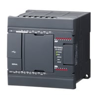
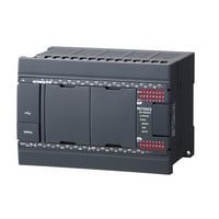
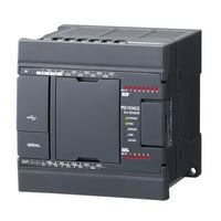
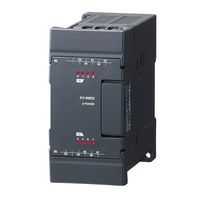
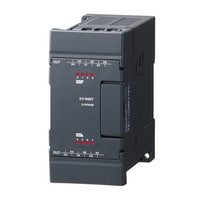
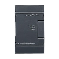
Terminal block type: Base unit, 14-point, Transistor output type
|
Model |
KV-N14AT |
KV-N14ATP |
KV-N14DT |
KV-N14DTP |
|||
|
Image |
|
|
|
|
|||
|
General specifications |
Power voltage |
100 to 240 VAC (+10%/-15%) |
24 VDC (+10%/-15%) |
||||
|
Operating ambient temperature |
0 to 55°C (no freezing)*1*2 |
||||||
|
Operating ambient humidity |
5 to 95% RH (no condensation)*1 |
||||||
|
Operating environment |
As little dust and corrosive gases as possible |
||||||
|
Noise immunity |
1500 V peak-to-peak or more, pulse width 1 µs, 50 ns (by noise simulator), IEC standard compliant (IEC61000-4-2/3/4/6) |
||||||
|
Withstand voltage |
1500 VAC for 1 minute, between power supply terminal and I/O terminals and between all external terminals and case |
||||||
|
Insulation resistance |
50 MΩ or more |
||||||
|
Output power supply voltage |
24 VDC (±10%; output capacity: 0.6 A) |
- |
|||||
|
Storage temperature |
-25 to +75°C |
||||||
|
Vibration resistance |
Intermittent vibration |
Frequency: 5 to 9 Hz |
Amplitude: 3.5 mm*3*4 |
||||
|
Frequency: 9 to 150 Hz |
Acceleration: 9.8 m/s2*3*5 |
||||||
|
Continuous vibration |
Frequency: 5 to 9 Hz |
Amplitude: 1.75 mm*3*5 |
|||||
|
Frequency: 9 to 150 Hz |
Acceleration: 4.9 m/s2*3*5 |
||||||
|
Shock resistance |
Acceleration: 150 m/s2, application time: 11 ms, two times in each of the X, Y, and Z directions |
||||||
|
Operating altitude |
2000 m or less |
||||||
|
Overvoltage category |
AC: II, DC: I |
||||||
|
Pollution degree |
2 |
||||||
|
Performance specifications |
Calculation control method |
Programme storage method |
|||||
|
I/O control method |
Refresh method |
||||||
|
Programming language |
Expanded ladder, KV Script, mnemonic |
||||||
|
Number of instructions |
Basic instructions: 81 kinds and 182 instructions, Application instructions: 39 kinds and 56 instructions |
||||||
|
Instruction execution speed |
Basic instruction: 50 ns minimum, Application instruction: 170 ns minimum |
||||||
|
Program capacity |
8k steps |
||||||
|
Maximum number of attachable I/O units |
3 |
||||||
|
Maximum number of I/O points |
128 (excluding the base unit I/O) |
||||||
|
Input relay/Output relay/Internal auxiliary relay |
R |
Total of 9600 points 1 bit (R000 to R59915) |
|||||
|
Link relay |
B |
8192 points 1 bit (B0 to B1FFF) |
|||||
|
Internal auxiliary relay |
MR |
9600 points 1 bit (MR000 to MR59915) |
|||||
|
Latch relay |
LR |
3200 points 1 bit (LR000 to LR19915) |
|||||
|
Control relay |
CR |
1440 points 1 bit (CR000 to CR8915) |
|||||
|
Timer |
T |
512 points 32 bits (T0 to T511) |
|||||
|
Counter |
C |
256 points 32 bits (C0 to C255) |
|||||
|
Data memory |
DM |
32768 points 16 bits (DM0 to DM32767) |
|||||
|
Link register |
W |
16384 points 16 bits (W0 to W3FFF) |
|||||
|
Temporary memory |
TM |
512 points 16 bits (TM0 to TM511) |
|||||
|
High-speed counter |
CTH |
2 points (CTH0 and CTH1) |
|||||
|
High-speed |
CTC |
4 points (CTC0 to CTC3) |
|||||
|
Index register |
Z |
12 points 32 bits (Z01 to Z12) |
|||||
|
Control memory |
CM |
9000 points 16 bits (CM0 to CM8999) |
|||||
|
Positioning pulse output |
2 axes |
||||||
|
Base unit I/O |
Input: 8 points, output: 6 points |
||||||
|
Number of comments and |
Device comment |
10000 |
|||||
|
Label |
14000 |
||||||
|
Power off hold function |
Programme memory |
Flash ROM can be rewritten 10000 times |
|||||
|
Device |
Nonvolatile RAM*8 |
||||||
|
Self-diagnosis function |
CPU error, RAM error, and other problems |
||||||
|
Input specifications |
Relay number |
General input: R000 to R003 (4 points), High-speed A-phase and B-phase input: R004 to R007 (2 channels, 4 points in total) |
|||||
|
Input mode |
24 VDC input (open collector) |
||||||
|
Maximum input voltage |
26.4 VDC |
||||||
|
Rated input voltage |
24 VDC (General input: 5.3 mA, High-speed A-phase and B-phase input: 6.5 mA*9) |
||||||
|
Minimum ON voltage |
19 VDC |
||||||
|
Maximum OFF current |
1.5 mA |
||||||
|
Common method |
General input: All inputs/common (1 terminal) |
||||||
|
Circuit delay time |
General input: |
||||||
|
Input time constant |
Normal: 10 ms, When the HSP instruction is used: 10 µs |
||||||
|
Delay by input time constant |
|||||||
|
Response frequency |
(High-speed A-phase and B-phase input) Single phase: 100 kHz, phase difference: 50 kHz, 24 V±10%, Duty 50% |
||||||
|
Output specifications |
Relay number |
General output: R504 to R505 (2 points), High-speed output: R500 to R503 (4 points) |
|||||
|
Output mode |
Sink output type |
Source output type |
Sink output type |
Source output type |
|||
|
Rated load |
30 VDC, 0.5 A |
||||||
|
Maximum OFF voltage |
30 VDC |
||||||
|
Leakage current at OFF |
100 µA or less |
||||||
|
Residual voltage at ON |
0.8 VDC or less (with 0.5 A output), 0.6 VDC or less (with 0.3 A output) |
||||||
|
Common method |
8 to 10 points/1 common |
||||||
|
ON/OFF response time |
General output: |
||||||
|
Overcurrent protection |
Protection provided for each common*11 |
||||||
|
Output frequency |
High-speed output: 100 kHz (7 to 100 mA load) |
||||||
|
Built-in serial port |
Interface |
Communication standard |
RS-232C |
||||
|
Connection |
Modular connector |
||||||
|
Transmission specifications RS-232C |
Baud rate |
1200, 2400, 4800, 9600, 19200, 38400, 57600, 115200 bps |
|||||
|
Transmission method |
Full duplex |
||||||
|
Data format |
Start bit |
1 bit |
|||||
|
Data bits |
7 bits, 8 bits |
||||||
|
Stop bits |
1 bit, 2 bits |
||||||
|
Error detection |
Parity |
Even, odd, none |
|||||
|
Transmission distance |
15 m |
||||||
|
Number of transmission units |
1 |
||||||
|
Indication |
SD (green), RD (red) |
||||||
|
Internal current consumption |
75 VA (VA is calculated with a power factor of 30%.) |
150 mA |
|||||
|
Weight |
Approx. 420 g |
Approx. 330 g |
|||||
|
*1 The range guaranteed as a system (excluding items specially noted for the units and cassettes). |
|||||||
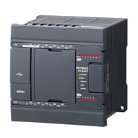
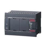
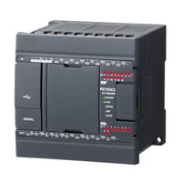
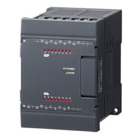
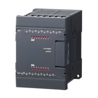
Terminal block type: Base unit, 24-point, Transistor output type
|
Model |
KV-N24AT |
KV-N24ATP |
KV-N24DT |
KV-N24DTP |
|||
|
Image |
|
|
|
|
|||
|
General specifications |
Power voltage |
100 to 240 VAC (+10%/-15%) |
24 VDC (+10%/-15%) |
||||
|
Operating ambient temperature |
0 to 55°C (no freezing)*1*2 |
||||||
|
Operating ambient humidity |
5 to 95% RH (no condensation)*1 |
||||||
|
Operating environment |
As little dust and corrosive gases as possible |
||||||
|
Noise immunity |
1500 V peak-to-peak or more, pulse width 1 µs, 50 ns (by noise simulator), IEC standard compliant (IEC61000-4-2/3/4/6) |
||||||
|
Withstand voltage |
1500 VAC for 1 minute, between power supply terminal and I/O terminals and between all external terminals and case |
||||||
|
Insulation resistance |
50 MΩ or more |
||||||
|
Output power supply voltage |
24 VDC (±10%; output capacity: 0.6 A) |
- |
|||||
|
Storage temperature |
-25 to +75°C |
||||||
|
Vibration resistance |
Intermittent vibration |
Frequency: 5 to 9 Hz |
Amplitude: 3.5 mm*3*4 |
||||
|
Frequency: 9 to 150 Hz |
Acceleration: 9.8 m/s2*3*5 |
||||||
|
Continuous vibration |
Frequency: 5 to 9 Hz |
Amplitude: 1.75 mm*3*5 |
|||||
|
Frequency: 9 to 150 Hz |
Acceleration: 4.9 m/s2*3*5 |
||||||
|
Shock resistance |
Acceleration: 150 m/s2, application time: 11 ms, two times in each of the X, Y, and Z directions |
||||||
|
Operating altitude |
2000 m or less |
||||||
|
Overvoltage category |
AC: II, DC: I |
||||||
|
Pollution degree |
2 |
||||||
|
Performance specifications |
Calculation control method |
Programme storage method |
|||||
|
I/O control method |
Refresh method |
||||||
|
Programming language |
Expanded ladder, KV Script, mnemonic |
||||||
|
Number of instructions |
Basic instructions: 81 kinds and 182 instructions, Application instructions: 39 kinds and 56 instructions |
||||||
|
Instruction execution speed |
Basic instruction: 50 ns minimum, Application instruction: 170 ns minimum |
||||||
|
Program capacity |
8k steps |
||||||
|
Maximum number of attachable I/O units |
8 |
||||||
|
Maximum number of I/O points |
256 (excluding the base unit I/O) |
||||||
|
Input relay/Output relay/Internal auxiliary relay |
R |
Total of 9600 points 1 bit (R000 to R59915) |
|||||
|
Link relay |
B |
8192 points 1 bit (B0 to B1FFF) |
|||||
|
Internal auxiliary relay |
MR |
9600 points 1 bit (MR000 to MR59915) |
|||||
|
Latch relay |
LR |
3200 points 1 bit (LR000 to LR19915) |
|||||
|
Control relay |
CR |
1440 points 1 bit (CR000 to CR8915) |
|||||
|
Timer |
T |
512 points 32 bits (T0 to T511) |
|||||
|
Counter |
C |
256 points 32 bits (C0 to C255) |
|||||
|
Data memory |
DM |
32768 points 16 bits (DM0 to DM32767) |
|||||
|
Link register |
W |
16384 points 16 bits (W0 to W3FFF) |
|||||
|
Temporary memory |
TM |
512 points 16 bits (TM0 to TM511) |
|||||
|
High-speed counter |
CTH |
2 points (CTH0 and CTH1) |
|||||
|
High-speed |
CTC |
4 points (CTC0 to CTC3) |
|||||
|
Index register |
Z |
12 points 32 bits (Z01 to Z12) |
|||||
|
Control memory |
CM |
9000 points 16 bits (CM0 to CM8999) |
|||||
|
Positioning pulse output |
2 axes |
||||||
|
Base unit I/O |
Input: 14 points; output: 10 points |
||||||
|
Number of comments and |
Device comment |
20000 |
|||||
|
Label |
28000 |
||||||
|
Power off hold function |
Programme memory |
Flash ROM can be rewritten 10000 times |
|||||
|
Device |
Nonvolatile RAM*8 |
||||||
|
Self-diagnosis function |
CPU error, RAM error, and other problems |
||||||
|
Input specifications |
Relay number |
General input: R000 to R003, R008 to R013 (10 points) |
|||||
|
Input mode |
24 VDC input (open collector) |
||||||
|
Maximum input voltage |
26.4 VDC |
||||||
|
Rated input voltage |
24 VDC (General input: 5.3 mA, High-speed A-phase and B-phase input: 6.5 mA*9) |
||||||
|
Minimum ON voltage |
19 VDC |
||||||
|
Maximum OFF current |
1.5 mA |
||||||
|
Common method |
General input: All inputs/common (1 terminal) |
||||||
|
Circuit delay time |
General input: |
||||||
|
Input time constant |
Normal: 10 ms, When the HSP instruction is used: 10 µs |
||||||
|
Delay by input time constant |
|||||||
|
Response frequency |
(High-speed A-phase and B-phase input) Single phase: 100 kHz, phase difference: 50 kHz, 24 V±10%, Duty 50% |
||||||
|
Output specifications |
Relay number |
General output: R504 to R509 (6 points), High-speed output: R500 to R503 (4 points) |
|||||
|
Output mode |
Sink output type |
Source output type |
Sink output type |
Source output type |
|||
|
Rated load |
30 VDC, 0.5 A |
||||||
|
Maximum OFF voltage |
30 VDC |
||||||
|
Leakage current at OFF |
100 µA or less |
||||||
|
Residual voltage at ON |
0.8 VDC or less (with 0.5 A output), 0.6 VDC or less (with 0.3 A output) |
||||||
|
Common method |
8 to 10 points/1 common |
||||||
|
ON/OFF response time |
General output: |
||||||
|
Overcurrent protection |
Protection provided for each common*11 |
||||||
|
Output frequency |
High-speed output: 100 kHz (7 to 100 mA load) |
||||||
|
Built-in serial port |
Interface |
Communication standard |
RS-232C |
||||
|
Connection |
Modular connector |
||||||
|
Transmission specifications RS-232C |
Baud rate |
1200, 2400, 4800, 9600, 19200, 38400, 57600, 115200 bps |
|||||
|
Transmission method |
Full duplex |
||||||
|
Data format |
Start bit |
1 bit |
|||||
|
Data bits |
7 bits, 8 bits |
||||||
|
Stop bits |
1 bit, 2 bits |
||||||
|
Error detection |
Parity |
Even, odd, none |
|||||
|
Transmission distance |
15 m |
||||||
|
Number of transmission units |
1 |
||||||
|
Indication |
SD (green), RD (red) |
||||||
|
Internal current consumption |
76 VA (VA is calculated with a power factor of 30%.) |
160 mA |
|||||
|
Weight |
Approx. 470 g |
Approx. 390 g |
|||||
|
*1 The range guaranteed as a system (excluding items specially noted for the units and cassettes). |
|||||||
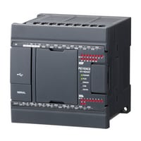
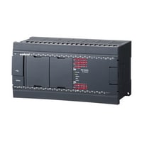
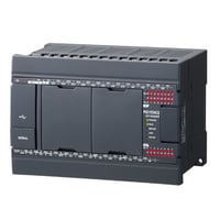
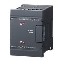
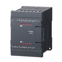
Terminal block type: Base unit, 40-point, Transistor output type
|
Model |
KV-N40AT |
KV-N40ATP |
KV-N40DT |
KV-N40DTP |
|||
|
Image |
|
|
|
|
|||
|
General specifications |
Power voltage |
100 to 240 VAC (+10%/-15%) |
24 VDC (+10%/-15%) |
||||
|
Operating ambient temperature |
0 to 55°C (no freezing)*1*2 |
||||||
|
Operating ambient humidity |
5 to 95% RH (no condensation)*1 |
||||||
|
Operating environment |
As little dust and corrosive gases as possible |
||||||
|
Noise immunity |
1500 V peak-to-peak or more, pulse width 1 µs, 50 ns (by noise simulator), IEC standard compliant (IEC61000-4-2/3/4/6) |
||||||
|
Withstand voltage |
1500 VAC for 1 minute, between power supply terminal and I/O terminals and between all external terminals and case |
||||||
|
Insulation resistance |
50 MΩ or more |
||||||
|
Output power supply voltage |
24 VDC (±10%; output capacity: 0.6 A) |
- |
|||||
|
Storage temperature |
-25 to +75°C |
||||||
|
Vibration resistance |
Intermittent vibration |
Frequency: 5 to 9 Hz |
Amplitude: 3.5 mm*3*4 |
||||
|
Frequency: 9 to 150 Hz |
Acceleration: 9.8 m/s2*3*5 |
||||||
|
Continuous vibration |
Frequency: 5 to 9 Hz |
Amplitude: 1.75 mm*3*5 |
|||||
|
Frequency: 9 to 150 Hz |
Acceleration: 4.9 m/s2*3*5 |
||||||
|
Shock resistance |
Acceleration: 150 m/s2, application time: 11 ms, two times in each of the X, Y, and Z directions |
||||||
|
Operating altitude |
2000 m or less |
||||||
|
Overvoltage category |
AC: II, DC: I |
||||||
|
Pollution degree |
2 |
||||||
|
Performance specifications |
Calculation control method |
Programme storage method |
|||||
|
I/O control method |
Refresh method |
||||||
|
Programming language |
Expanded ladder, KV Script, mnemonic |
||||||
|
Number of instructions |
Basic instructions: 81 kinds and 182 instructions, Application instructions: 39 kinds and 56 instructions |
||||||
|
Instruction execution speed |
Basic instruction: 50 ns minimum, Application instruction: 170 ns minimum |
||||||
|
Program capacity |
16k steps |
||||||
|
Maximum number of attachable I/O units |
8 |
||||||
|
Maximum number of I/O points |
256 (excluding the base unit I/O) |
||||||
|
Input relay/Output relay/Internal auxiliary relay |
R |
Total of 9600 points 1 bit (R000 to R59915) |
|||||
|
Link relay |
B |
8192 points 1 bit (B0 to B1FFF) |
|||||
|
Internal auxiliary relay |
MR |
9600 points 1 bit (MR000 to MR59915) |
|||||
|
Latch relay |
LR |
3200 points 1 bit (LR000 to LR19915) |
|||||
|
Control relay |
CR |
1440 points 1 bit (CR000 to CR8915) |
|||||
|
Timer |
T |
512 points 32 bits (T0 to T511) |
|||||
|
Counter |
C |
256 points 32 bits (C0 to C255) |
|||||
|
Data memory |
DM |
32768 points 16 bits (DM0 to DM32767) |
|||||
|
Link register |
W |
16384 points 16 bits (W0 to W3FFF) |
|||||
|
Temporary memory |
TM |
512 points 16 bits (TM0 to TM511) |
|||||
|
High-speed counter |
CTH |
3 points (CTH0 to CTH2) |
|||||
|
High-speed |
CTC |
6 points (CTC0 to CTC5) |
|||||
|
Index register |
Z |
12 points 32 bits (Z01 to Z12) |
|||||
|
Control memory |
CM |
9000 points 16 bits (CM0 to CM8999) |
|||||
|
Positioning pulse output |
3 axes |
||||||
|
Base unit I/O |
Input: 24 points, output: 16 points |
||||||
|
Number of comments and |
Device comment |
20000 |
|||||
|
Label |
28000 |
||||||
|
Power off hold function |
Programme memory |
Flash ROM can be rewritten 10000 times |
|||||
|
Device |
Nonvolatile RAM*8 |
||||||
|
Self-diagnosis function |
CPU error, RAM error, and other problems |
||||||
|
Input specifications |
Relay number |
General input: R000 to R007, R014 to R107 (18 points) |
|||||
|
Input mode |
24 VDC input (open collector) |
||||||
|
Maximum input voltage |
26.4 VDC |
||||||
|
Rated input voltage |
24 VDC (General input: 5.3 mA, High-speed A-phase and B-phase input: 6.5 mA*9) |
||||||
|
Minimum ON voltage |
19 VDC |
||||||
|
Maximum OFF current |
1.5 mA |
||||||
|
Common method |
General input: All inputs/common (1 terminal) |
||||||
|
Circuit delay time |
General input: |
||||||
|
Input time constant |
Normal: 10 ms, When the HSP instruction is used: 10 µs |
||||||
|
Delay by input time constant |
|||||||
|
Response frequency |
(High-speed A-phase and B-phase input) Single phase: 100 kHz, phase difference: 50 kHz, 24 V±10%, Duty 50% |
||||||
|
Output specifications |
Relay number |
General output: R506 to R515 (10 points), High-speed output: R500 to R505 (6 points) |
|||||
|
Output mode |
Sink output type |
Source output type |
Sink output type |
Source output type |
|||
|
Rated load |
30 VDC, 0.5 A |
||||||
|
Maximum OFF voltage |
30 VDC |
||||||
|
Leakage current at OFF |
100 µA or less |
||||||
|
Residual voltage at ON |
0.8 VDC or less (with 0.5 A output), 0.6 VDC or less (with 0.3 A output) |
||||||
|
Common method |
8 to 10 points/1 common |
||||||
|
ON/OFF response time |
General output: |
||||||
|
Overcurrent protection |
Protection provided for each common*11 |
||||||
|
Output frequency |
High-speed output: 100 kHz (7 to 100 mA load) |
||||||
|
Built-in serial port |
Interface |
Communication standard |
RS-232C |
||||
|
Connection |
Modular connector |
||||||
|
Transmission specifications RS-232C |
Baud rate |
1200, 2400, 4800, 9600, 19200, 38400, 57600, 115200 bps |
|||||
|
Transmission method |
Full duplex |
||||||
|
Data format |
Start bit |
1 bit |
|||||
|
Data bits |
7 bits, 8 bits |
||||||
|
Stop bits |
1 bit, 2 bits |
||||||
|
Error detection |
Parity |
Even, odd, none |
|||||
|
Transmission distance |
15 m |
||||||
|
Number of transmission units |
1 |
||||||
|
Indication |
SD (green), RD (red) |
||||||
|
Internal current consumption |
82 VA (VA is calculated with a power factor of 30%.) |
250 mA |
|||||
|
Weight |
Approx. 620 g |
Approx. 530 g |
|||||
|
*1 The range guaranteed as a system (excluding items specially noted for the units and cassettes). |
|||||||
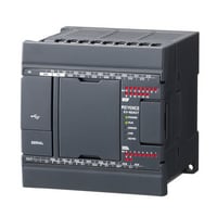
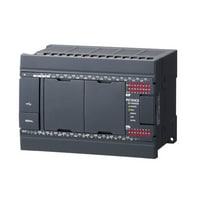
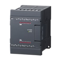
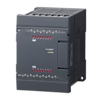
Terminal block type: Base unit, 60-point, Transistor output type
|
Model |
KV-N60AT |
KV-N60ATP |
|||
|
Image |
|
|
|||
|
General specifications |
Power voltage |
100 to 240 VAC (+10%/-15%) |
|||
|
Operating ambient temperature |
0 to 55°C (no freezing)*1*2 |
||||
|
Operating ambient humidity |
5 to 95% RH (no condensation)*1 |
||||
|
Operating environment |
As little dust and corrosive gases as possible |
||||
|
Noise immunity |
1500 V peak-to-peak or more, pulse width 1 µs, 50 ns (by noise simulator), IEC standard compliant (IEC61000-4-2/3/4/6) |
||||
|
Withstand voltage |
1500 VAC for 1 minute, between power supply terminal and I/O terminals and between all external terminals and case |
||||
|
Insulation resistance |
50 MΩ or more |
||||
|
Output power supply voltage |
24 VDC (±10%; output capacity: 0.6 A) |
||||
|
Storage temperature |
-25 to +75°C |
||||
|
Vibration resistance |
Intermittent vibration |
Frequency: 5 to 9 Hz |
Amplitude: 3.5 mm*3*4 |
||
|
Frequency: 9 to 150 Hz |
Acceleration: 9.8 m/s2*3*5 |
||||
|
Continuous vibration |
Frequency: 5 to 9 Hz |
Amplitude: 1.75 mm*3*5 |
|||
|
Frequency: 9 to 150 Hz |
Acceleration: 4.9 m/s2*3*5 |
||||
|
Shock resistance |
Acceleration: 150 m/s2, application time: 11 ms, two times in each of the X, Y, and Z directions |
||||
|
Operating altitude |
2000 m or less |
||||
|
Overvoltage category |
AC: II, DC: I |
||||
|
Pollution degree |
2 |
||||
|
Performance specifications |
Calculation control method |
Programme storage method |
|||
|
I/O control method |
Refresh method |
||||
|
Programming language |
Expanded ladder, KV Script, mnemonic |
||||
|
Number of instructions |
Basic instructions: 81 kinds and 182 instructions, Application instructions: 39 kinds and 56 instructions |
||||
|
Instruction execution speed |
Basic instruction: 50 ns minimum, Application instruction: 170 ns minimum |
||||
|
Program capacity |
16k steps |
||||
|
Maximum number of attachable I/O units |
8 |
||||
|
Maximum number of I/O points |
256 (excluding the base unit I/O) |
||||
|
Input relay/Output relay/Internal auxiliary relay |
R |
Total of 9600 points 1 bit (R000 to R59915) |
|||
|
Link relay |
B |
8192 points 1 bit (B0 to B1FFF) |
|||
|
Internal auxiliary relay |
MR |
9600 points 1 bit (MR000 to MR59915) |
|||
|
Latch relay |
LR |
3200 points 1 bit (LR000 to LR19915) |
|||
|
Control relay |
CR |
1440 points 1 bit (CR000 to CR8915) |
|||
|
Timer |
T |
512 points 32 bits (T0 to T511) |
|||
|
Counter |
C |
256 points 32 bits (C0 to C255) |
|||
|
Data memory |
DM |
32768 points 16 bits (DM0 to DM32767) |
|||
|
Link register |
W |
16384 points 16 bits (W0 to W3FFF) |
|||
|
Temporary memory |
TM |
512 points 16 bits (TM0 to TM511) |
|||
|
High-speed counter |
CTH |
4 points (CTH0 to CTH3) |
|||
|
High-speed |
CTC |
8 points (CTC0 to CTC7) |
|||
|
Index register |
Z |
12 points 32 bits (Z01 to Z12) |
|||
|
Control memory |
CM |
9000 points 16 bits (CM0 to CM8999) |
|||
|
Positioning pulse output |
4 axes |
||||
|
Base unit I/O |
Input: 36 points, output: 24 points |
||||
|
Number of comments and |
Device comment |
20000 |
|||
|
Label |
28000 |
||||
|
Power off hold function |
Programme memory |
Flash ROM can be rewritten 10000 times |
|||
|
Device |
Nonvolatile RAM*8 |
||||
|
Self-diagnosis function |
CPU error, RAM error, and other problems |
||||
|
Input specifications |
Relay number |
General input: R000 to R007, R100 to R203 (28 points)*9 |
|||
|
Input mode |
24 VDC input (open collector) |
||||
|
Maximum input voltage |
26.4 VDC |
||||
|
Rated input voltage |
24 VDC (General input: 5.3 mA, High-speed A-phase and B-phase input: 6.5 mA*10) |
||||
|
Minimum ON voltage |
19 VDC |
||||
|
Maximum OFF current |
1.5 mA |
||||
|
Common method |
General input: All inputs/common (1 terminal) |
||||
|
Circuit delay time |
General input (below for R108 to R203): |
||||
|
Input time constant |
Normal: 10 ms, When the HSP instruction is used: 10 µs |
||||
|
Delay by input time constant |
|||||
|
Response frequency |
(High-speed A-phase and B-phase input) Single phase: 100 kHz, phase difference: 50 kHz, 24 V±10%, Duty 50% |
||||
|
Output specifications |
Relay number |
General output: R508 to R607 (16 points), High-speed output: R500 to R507 (8 points) |
|||
|
Output mode |
Sink output type |
Source output type |
|||
|
Rated load |
30 VDC, 0.5 A |
||||
|
Maximum OFF voltage |
30 VDC |
||||
|
Leakage current at OFF |
100 µA or less |
||||
|
Residual voltage at ON |
0.8 VDC or less (with 0.5 A output), 0.6 VDC or less (with 0.3 A output) |
||||
|
Common method |
8 to 10 points/1 common |
||||
|
ON/OFF response time |
General output: |
||||
|
Overcurrent protection |
Protection provided for each common*12 |
||||
|
Output frequency |
High-speed output: 100 kHz (7 to 100 mA load) |
||||
|
Built-in serial port |
Interface |
Communication standard |
RS-232C |
||
|
Connection |
Modular connector |
||||
|
Transmission specifications RS-232C |
Baud rate |
1200, 2400, 4800, 9600, 19200, 38400, 57600, 115200 bps |
|||
|
Transmission method |
Full duplex |
||||
|
Data format |
Start bit |
1 bit |
|||
|
Data bits |
7 bits, 8 bits |
||||
|
Stop bits |
1 bit, 2 bits |
||||
|
Error detection |
Parity |
Even, odd, none |
|||
|
Transmission distance |
15 m |
||||
|
Number of transmission units |
1 |
||||
|
Indication |
SD (green), RD (red) |
||||
|
Internal current consumption |
85 VA (VA is calculated with a power factor of 30%.) |
||||
|
Weight |
Approx. 750 g |
||||
|
*1 The range guaranteed as a system (excluding items specially noted for the units and cassettes). |
|||||
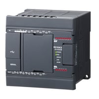
Terminal block type: Base unit, 14/24-point, Relay output type
|
Model |
KV-N14AR |
KV-N14DR |
KV-N24AR |
KV-N24DR |
|||
|
Image |
|
|
|
|
|||
|
General specifications |
Power voltage |
100 to 240 VAC (+10%/-15%) |
24 VDC (+10%/-15%) |
100 to 240 VAC (+10%/-15%) |
24 VDC (+10%/-15%) |
||
|
Operating ambient temperature |
0 to 55°C (no freezing)*1*2 |
||||||
|
Operating ambient humidity |
5 to 95% RH (no condensation)*1 |
||||||
|
Operating environment |
As little dust and corrosive gases as possible |
||||||
|
Noise immunity |
1500 V peak-to-peak or more, pulse width 1 µs, 50 ns (by noise simulator), IEC standard compliant (IEC61000-4-2/3/4/6) |
||||||
|
Withstand voltage |
1500 VAC for 1 minute, between power supply terminal and I/O terminals and between all external terminals and case |
||||||
|
Insulation resistance |
50 MΩ or more |
||||||
|
Output power supply voltage |
24 VDC (±10%; output capacity: 0.6 A) |
- |
24 VDC (±10%; output capacity: 0.6 A) |
- |
|||
|
Storage temperature |
-25 to +75°C |
||||||
|
Vibration resistance |
Intermittent vibration |
Frequency: 5 to 9 Hz |
Amplitude: 3.5 mm*3*4 |
||||
|
Frequency: 9 to 150 Hz |
Acceleration: 9.8 m/s2*3*4 |
||||||
|
Continuous vibration |
Frequency: 5 to 9 Hz |
Amplitude: 1.75 mm*3*4 |
|||||
|
Frequency: 9 to 150 Hz |
Acceleration: 4.9 m/s2*3*4 |
||||||
|
Shock resistance |
Acceleration: 150 m/s2, application time: 11 ms, two times in each of the X, Y, and Z directions |
||||||
|
Operating altitude |
2000 m or less |
||||||
|
Overvoltage category |
AC: II, DC: I |
||||||
|
Pollution degree |
2 |
||||||
|
Performance specifications |
Calculation control method |
Programme storage method |
|||||
|
I/O control method |
Refresh method |
||||||
|
Programming language |
Expansion ladder, KV script, mnemonic |
Expanded ladder, KV Script, mnemonic |
|||||
|
Number of instructions |
Basic instructions: 81 kinds and 182 instructions, Application instructions: 39 kinds and 56 instructions |
||||||
|
Instruction execution speed |
Basic instruction: 50 ns minimum, Application instruction: 170 ns minimum |
||||||
|
Program capacity |
8k steps |
||||||
|
Maximum number of attachable I/O units |
3 |
8 |
|||||
|
Maximum number of I/O points |
128 (excluding the base unit I/O) |
256 (excluding the base unit I/O) |
|||||
|
Input relay/Output relay/Internal auxiliary relay |
R |
Total of 9600 points 1 bit (R000 to R59915) |
|||||
|
Link relay |
B |
8192 points 1 bit (B0 to B1FFF) |
|||||
|
Internal auxiliary relay |
MR |
9600 points 1 bit (MR000 to MR59915) |
|||||
|
Latch relay |
LR |
3200 points 1 bit (LR000 to LR19915) |
|||||
|
Control relay |
CR |
1440 points 1 bit (CR000 to CR8915) |
|||||
|
Timer |
T |
512 points 32 bits (T0 to T511) |
|||||
|
Counter |
C |
256 points 32 bits (C0 to C255) |
|||||
|
Data memory |
DM |
32768 points 16 bits (DM0 to DM32767) |
|||||
|
Link register |
W |
16384 points 16 bits (W0 to W3FFF) |
|||||
|
Temporary memory |
TM |
512 points 16 bits (TM0 to TM511) |
|||||
|
High-speed counter |
CTH |
2 points (CTH0 and CTH1) |
|||||
|
High-speed |
CTC |
4 points (CTC0 to CTC3) |
|||||
|
Index register |
Z |
12 points 32 bits (Z01 to Z12) |
|||||
|
Control memory |
CM |
9000 points 16 bits (CM0 to CM8999) |
|||||
|
Base unit I/O |
Input: 8 points, output: 6 points |
Input: 14 points; output: 10 points |
|||||
|
Number of comments and |
Device comment |
10000 |
20000 |
||||
|
Label |
14000 |
28000 |
|||||
|
Power off hold function |
Programme memory |
Flash ROM can be rewritten 10000 times |
|||||
|
Device |
Nonvolatile RAM*7 |
||||||
|
Self-diagnosis function |
CPU error, RAM error, and other problems |
||||||
|
Input specifications |
Relay number |
General input: R000 to R003 (4 points), High-speed A-phase and B-phase input: R004 to R007 (2 channels, 4 points in total) |
General input: R000 to R003, R008 to R013 (10 points) |
||||
|
Input mode |
24 VDC input (open collector) |
||||||
|
Maximum input voltage |
26.4 VDC |
||||||
|
Rated input voltage |
24 VDC (General input: 5.3 mA, High-speed A-phase and B-phase input: 6.5 mA*8) |
||||||
|
Minimum ON voltage |
19 VDC |
||||||
|
Maximum OFF current |
1.5 mA |
||||||
|
Common method |
General input: All inputs/common (1 terminal) |
||||||
|
Circuit delay time |
General input: |
||||||
|
Input time constant |
Normal: 10 ms, When the HSP instruction is used: 10 µs |
||||||
|
Delay by input time constant |
|||||||
|
Response frequency |
(High-speed A-phase and B-phase input) Single phase: 100 kHz, phase difference: 50 kHz, 24 V±10%, Duty 50% |
||||||
|
Output specifications |
Relay number |
R500 to R505 (6 points) |
R500 to R509 (10 points) |
||||
|
Output mode |
Relay |
||||||
|
Rated load |
250 VAC/30 VDC, 2 A |
||||||
|
Common method |
2 to 4 points/1 common |
||||||
|
ON/OFF response time |
10 ms or less |
||||||
|
ON resistance |
50m Ω or less |
||||||
|
Minimum applicable load |
100 µA/100 mVDC |
||||||
|
Relay life |
Electrical: 100000 cycles or more (20 cycles/minute), Mechanical: 20000000 cycles or more |
||||||
|
Relay replacement |
Impossible |
||||||
|
Built-in serial port |
Interface |
Communication standard |
RS-232C |
||||
|
Connection |
Modular connector |
||||||
|
Transmission specifications RS-232C |
Baud rate |
1200, 2400, 4800, 9600, 19200, 38400, 57600, 115200 bps |
|||||
|
Transmission method |
Full duplex |
||||||
|
Data format |
Start bit |
1 bit |
|||||
|
Data bits |
7 bits, 8 bits |
||||||
|
Stop bits |
1 bit, 2 bits |
||||||
|
Error detection |
Parity |
Even, odd, none |
|||||
|
Transmission distance |
15 m |
||||||
|
Number of transmission units |
1 |
||||||
|
Indication |
SD (green), RD (red) |
||||||
|
Internal current consumption |
76 VA |
160 mA |
79 VA |
190 mA |
|||
|
Weight |
Approx. 430 g |
Approx. 350 g |
Approx. 500 g |
Approx. 420 g |
|||
|
*1 The range guaranteed as a system (excluding items specially noted for the units and cassettes). |
|||||||

Terminal block type: Base unit, 40/60-point, Relay output type
|
Model |
KV-N40AR |
KV-N40DR |
KV-N60AR |
|||
|
Image |
|
|
|
|||
|
General specifications |
Power voltage |
100 to 240 VAC (+10%/-15%) |
24 VDC (+10%/-15%) |
100 to 240 VAC (+10%/-15%) |
||
|
Operating ambient temperature |
0 to 55°C (no freezing)*1*2 |
|||||
|
Operating ambient humidity |
5 to 95% RH (no condensation)*1 |
|||||
|
Operating environment |
As little dust and corrosive gases as possible |
|||||
|
Noise immunity |
1500 V peak-to-peak or more, pulse width 1 µs, 50 ns (by noise simulator), IEC standard compliant (IEC61000-4-2/3/4/6) |
|||||
|
Withstand voltage |
1500 VAC for 1 minute, between power supply terminal and I/O terminals and between all external terminals and case |
|||||
|
Insulation resistance |
50 MΩ or more |
|||||
|
Output power supply voltage |
24 VDC (±10%; output capacity: 0.6 A) |
- |
24 VDC (±10%; output capacity: 0.6 A) |
|||
|
Storage temperature |
-25 to +75°C |
|||||
|
Vibration resistance |
Intermittent vibration |
Frequency: 5 to 9 Hz |
Amplitude: 3.5 mm*3*4 |
|||
|
Frequency: 9 to 150 Hz |
Acceleration: 9.8 m/s2*3*4 |
|||||
|
Continuous vibration |
Frequency: 5 to 9 Hz |
Amplitude: 1.75 mm*3*4 |
||||
|
Frequency: 9 to 150 Hz |
Acceleration: 4.9 m/s2*3*4 |
|||||
|
Shock resistance |
Acceleration: 150 m/s2, application time: 11 ms, two times in each of the X, Y, and Z directions |
|||||
|
Operating altitude |
2000 m or less |
|||||
|
Overvoltage category |
AC: II, DC: I |
|||||
|
Pollution degree |
2 |
|||||
|
Performance specifications |
Calculation control method |
Programme storage method |
||||
|
I/O control method |
Refresh method |
|||||
|
Programming language |
Expanded ladder, KV Script, mnemonic |
|||||
|
Number of instructions |
Basic instructions: 81 kinds and 182 instructions, Application instructions: 39 kinds and 56 instructions |
|||||
|
Instruction execution speed |
Basic instruction: 50 ns minimum, Application instruction: 170 ns minimum |
|||||
|
Program capacity |
16k steps |
|||||
|
Maximum number of attachable I/O units |
8 |
|||||
|
Maximum number of I/O points |
256 (excluding the base unit I/O) |
|||||
|
Input relay/Output relay/Internal auxiliary relay |
R |
Total of 9600 points 1 bit (R000 to R59915) |
||||
|
Link relay |
B |
8192 points 1 bit (B0 to B1FFF) |
||||
|
Internal auxiliary relay |
MR |
9600 points 1 bit (MR000 to MR59915) |
||||
|
Latch relay |
LR |
3200 points 1 bit (LR000 to LR19915) |
||||
|
Control relay |
CR |
1440 points 1 bit (CR000 to CR8915) |
||||
|
Timer |
T |
512 points 32 bits (T0 to T511) |
||||
|
Counter |
C |
256 points 32 bits (C0 to C255) |
||||
|
Data memory |
DM |
32768 points 16 bits (DM0 to DM32767) |
||||
|
Link register |
W |
16384 points 16 bits (W0 to W3FFF) |
||||
|
Temporary memory |
TM |
512 points 16 bits (TM0 to TM511) |
||||
|
High-speed counter |
CTH |
3 points (CTH0 to CTH2) |
4 points (CTH0 to CTH3) |
|||
|
High-speed |
CTC |
6 points (CTC0 to CTC5) |
8 points (CTC0 to CTC7) |
|||
|
Index register |
Z |
12 points 32 bits (Z01 to Z12) |
||||
|
Control memory |
CM |
9000 points 16 bits (CM0 to CM8999) |
||||
|
Base unit I/O |
Input: 24 points, output: 16 points |
Input: 36 points, output: 24 points |
||||
|
Number of comments and |
Device comment |
20000 |
||||
|
Label |
28000 |
|||||
|
Power off hold function |
Programme memory |
Flash ROM can be rewritten 10000 times |
||||
|
Device |
Nonvolatile RAM*7 |
|||||
|
Self-diagnosis function |
CPU error, RAM error, and other problems |
|||||
|
Input specifications |
Relay number |
General input: R000 to R007, R014 to R107 (18 points) |
General input: R000 to R007, R100 to R203 (28 points)*10 |
|||
|
Input mode |
24 VDC input (open collector) |
|||||
|
Maximum input voltage |
26.4 VDC |
|||||
|
Rated input voltage |
24 VDC (General input: 5.3 mA, High-speed A-phase and B-phase input: 6.5 mA*8) |
|||||
|
Minimum ON voltage |
19 VDC |
|||||
|
Maximum OFF current |
1.5 mA |
|||||
|
Common method |
General input: All inputs/common (1 terminal) |
|||||
|
Circuit delay time |
General input: |
General input (below for R108 to R203): |
||||
|
Input time constant |
Normal: 10 ms, When the HSP instruction is used: 10 µs |
|||||
|
Delay by input time constant |
||||||
|
Response frequency |
(High-speed A-phase and B-phase input) Single phase: 100 kHz, phase difference: 50 kHz, 24 V±10%, Duty 50% |
|||||
|
Output specifications |
Relay number |
R500 to R515 (16 points) |
R500 to R607 (24 points) |
|||
|
Output mode |
Relay |
|||||
|
Rated load |
250 VAC/30 VDC, 2 A |
|||||
|
Common method |
2 to 4 points/1 common |
|||||
|
ON/OFF response time |
10 ms or less |
|||||
|
ON resistance |
50m Ω or less |
|||||
|
Minimum applicable load |
100 µA/100 mVDC |
|||||
|
Relay life |
Electrical: 100000 cycles or more (20 cycles/minute), Mechanical: 20000000 cycles or more |
|||||
|
Relay replacement |
Impossible |
|||||
|
Built-in serial port |
Interface |
Communication standard |
RS-232C |
|||
|
Connection |
Modular connector |
|||||
|
Transmission specifications RS-232C |
Baud rate |
1200, 2400, 4800, 9600, 19200, 38400, 57600, 115200 bps |
||||
|
Transmission method |
Full duplex |
|||||
|
Data format |
Start bit |
1 bit |
||||
|
Data bits |
7 bits, 8 bits |
|||||
|
Stop bits |
1 bit, 2 bits |
|||||
|
Error detection |
Parity |
Even, odd, none |
||||
|
Transmission distance |
15 m |
|||||
|
Number of transmission units |
1 |
|||||
|
Indication |
SD (green), RD (red) |
|||||
|
Internal current consumption |
86 VA |
280 mA |
91 VA |
|||
|
Weight |
Approx. 660 g |
Approx. 580 g |
Approx. 820 g |
|||
|
*1 The range guaranteed as a system (excluding items specially noted for the units and cassettes). |
||||||

Terminal block type: Expansion input unit
|
Model |
KV-N8EX |
KV-N16EX |
|||
|
Image |
|
|
|||
|
Expansion input unit |
External connection method |
Terminal block |
|||
|
Input terminals |
24 VDC mode, 5 VDC mode |
||||
|
Maximum input voltage |
26.4 VDC |
||||
|
Input rated voltage |
24 VDC mode |
5.3mA |
|||
|
5 VDC mode |
1mA |
||||
|
Minimum ON voltage |
24 VDC mode |
19V |
|||
|
5 VDC mode |
3.5V |
||||
|
Maximum OFF voltage |
24 VDC mode |
1.5mA |
|||
|
5 VDC mode |
1.5V |
||||
|
Common method |
8 points/1 common (2 terminals)*1 |
16 points/1 common (2 terminals)*1 |
|||
|
Input time constant (four-level switching) |
Input time constant setting |
OFF to ON: Typ. |
25µs : 10µs |
||
|
OFF to ON: Max. |
25µs : 50µs |
||||
|
ON to OFF: Typ. |
25µs : 50µs |
||||
|
ON to OFF: Max. |
25µs : 150µs |
||||
|
Input impedance |
4.3kΩ |
||||
|
Internal current consumption |
20mA or less |
||||
|
Weight |
Approx. 150 g |
Approx. 220 g |
|||
|
*1 The KV-N8EX and KV-N16EX have 2 COM terminals, but these are shared internally. |
|||||
Terminal block type: Expansion output unit
|
Model |
KV-N8ER |
KV-N16ER |
KV-N8ET |
KV-N8ETP |
KV-N16ET |
KV-N16ETP |
|||
|
Image |
|
|
|
|
|
|
|||
|
Expansion output unit |
Output Points |
8 points |
16 points |
8 points |
16 points |
||||
|
External connectionmethod |
Relay |
MOSFET |
|||||||
|
External connection method |
Terminal block |
||||||||
|
Rated load |
250 VAC/30 VDC, 2 A |
30 VDC, 0.5 A |
|||||||
|
Leakage current (when output is OFF) |
− |
100 μA or less |
|||||||
|
Residual voltage (at ON) |
0.8 VDC or less (with 0.5 A output) |
||||||||
|
ON resistance |
50 mΩ or less |
− |
|||||||
|
Common method |
Independent |
4 points/1 common |
8 points/1 common |
16 points/1 common |
|||||
|
Response time |
OFF to ON |
10 ms or less |
100 μs or less (with a load of 1 mA or more) |
||||||
|
ON to OFF |
200 μs or less (with a load of 1 mA or more) |
||||||||
|
Relay life |
Electrical: 100000 cycles or more (20 cycles/minute) |
− |
|||||||
|
Relay replacement |
Impossible |
||||||||
|
Internal current consumption |
60 mA or less |
100 mA or less |
30 mA or less |
40 mA or less |
|||||
|
Weight |
Approx. 230 g |
Approx. 260 g |
Approx. 160 g |
Approx. 210 g |
|||||
|
*1 The KV-N16ER has two terminals for each of C0, C1, C2, and C3 respectively, which are shorted internally. (C0, C1, C2, and C3 are independent.) |
|||||||||
Terminal block type: Expansion I/O unit
|
Model |
KV-N8EXR |
KV-N8EXT |
|||
|
Image |
|
|
|||
|
Expansion input unit |
External connection method |
Terminal block |
|||
|
Input Points |
8 |
||||
|
Input terminals |
24 VDC mode, 5 VDC mode |
||||
|
Maximum input voltage |
26.4 VDC |
||||
|
Input rated voltage |
24 VDC mode |
5.3mA |
|||
|
5 VDC mode |
1mA |
||||
|
Minimum ON voltage |
24 VDC mode |
19V |
|||
|
5 VDC mode |
3.5V |
||||
|
Maximum OFF voltage |
24 VDC mode |
1.5mA |
|||
|
5 VDC mode |
1.5V |
||||
|
Common method |
8 points/1 common (1 terminal)*1 |
8 points/1 common (2 terminals)*1 |
|||
|
Input time constant (four-level switching) |
Input time constant setting |
OFF to ON: Typ. |
25µs : 10µs |
||
|
OFF to ON: Max. |
25µs : 50µs |
||||
|
ON to OFF: Typ. |
25µs : 50µs |
||||
|
ON to OFF: Max. |
25µs : 150µs |
||||
|
Input impedance |
4.3kΩ |
||||
|
Expansion output unit |
Output Points |
8 |
|||
|
External connectionmethod |
Relay |
MOSFET (N-ch) |
|||
|
Rated load |
250 VAC/30 VDC, 2 A |
30 VDC, 0.5 A |
|||
|
Leakage current (when output is OFF) |
― |
100µA or less |
|||
|
Residual voltage (at ON) |
0.8 VDC or less (with 0.5 A output), 0.6 VDC or less (with 0.3 A output) |
||||
|
ON resistance |
50mΩ or less |
― |
|||
|
Common method |
4 points/1 common |
8 points/1 common |
|||
|
Response time |
OFF to ON |
10ms or less |
100 µs or less |
||
|
ON to OFF |
200 µs or less |
||||
|
Relay life |
Electrical : 100000 cycles or more (20 cycles/minute) Mechanical : 20000000 cycles or more |
― |
|||
|
Relay replacement |
Not possible |
||||
|
Internal current consumption |
60mA or less |
30mA or less |
|||
|
Weight |
Approx. 230 g |
Approx. 210 g |
|||
|
*1 The input COM and output COM terminals are independent. |
|||||
Terminal block type: Extension access window cassette
|
Model |
KV-N1AW |
|||
|
Image |
|
|||
|
General specifications |
Power voltage |
Supplied from the base unit |
||
|
Operating ambient temperature |
0 to +55°C (no freezing)*1*2 |
|||
|
Operating ambient humidity |
5 to 90% RH (no condensation)*3 |
|||
|
Noise immunity |
1500 V peak-to-peak or more, pulse width 1 µs, 50 ns (by noise simulator), IEC standard compliant (IEC61000-4-2/3/4/6) |
|||
|
Insulation resistance |
50 MΩ or more |
|||
|
Storage temperature |
-25 to +75°C |
|||
|
Base Unit |
Storage relative humidity |
35 to 85% RH (no condensation)*3 |
||
|
Vibration resistance |
Intermittent vibration |
Frequency: 5 to 9 Hz |
Amplitude : 3.5 mm*4 |
|
|
Frequency: 9 to 150 Hz |
Acceleration : 9.8 m/s2*4 |
|||
|
Continuous vibration |
Frequency: 5 to 9 Hz |
Amplitude : 1.75 mm*4 |
||
|
Frequency: 9 to 150 Hz |
Acceleration : 4.9 m/s2*4 |
|||
|
Shock resistance |
Acceleration : 150 m/s2 , application time : 11 ms, two times in each of the X, Y, and Z directions |
|||
|
Base Unit |
Altitude |
2000m or less |
||
|
Pollution degree |
2 |
|||
|
Extension access window cassette |
Number of times |
200 |
||
|
Memory save method |
Flash ROM can be rewritten 10000 times |
|||
|
Weight |
Approx. 30 g |
|||
|
*1 This is the guaranteed range of the system |
||||

Terminal block type: Extension serial communication cassette
|
Model |
KV-N10L |
KV-N11L |
|||
|
Image |
|
|
|||
|
Transmission |
Electrical termination (Terminator) |
― |
Set with the switch on the front panel of the main unit |
||
|
Baud rate |
1200, 2400, 4800, 9600, 19200, 38400, 57600, 115200bps |
||||
|
Transmission method |
Full duplex |
RS-422A/RS-485 (4-wire) : Full douplex, RS-485 (2-wire) : Half douplex |
|||
|
Data format |
Start bit |
1 bit |
|||
|
Data bits |
7 bit, 8 bit |
||||
|
Stop bits |
1 bit, 2 bit |
||||
|
Error detection |
Parity |
Even, odd, none |
|||
|
RS/CS flow control |
Enabled, disabled |
― |
|||
|
Interface |
Communication standard |
RS-232C |
RS-422A/RS-485 (4-wire), RS-485 (2-wire) |
||
|
Connection |
D-sub 9-pin |
European terminal block (cannot be removed or reconnected) |
|||
|
Transmission |
Transmission distance |
15m |
Extendable up to 1200 m*1 |
||
|
Number of transmission units |
1 |
32*1 |
|||
|
Indication |
SD (orange), RD (orange) |
||||
|
Weight |
Approx. 30 g |
||||
|
*1 This varies depending on the model. For details, see the KV Nano Series “Serial Communication Function User's Manual.” |
|||||

Terminal block type: Analogue I/O unit
|
Model |
KV-N3AM |
|||
|
Image |
|
|||
|
Conversion speed |
80 µs/channel*1 |
|||
|
Conversion |
A/D conversion, D/A conversion |
|||
|
Points |
A/D conversion : 2 (single end), D/A conversion : 1 |
|||
|
Range/resolution |
Voltage |
-10 V to +10 V |
A/D conversion : 1/8000 2.5 mV, D/A conversion : 1/8000 2.5 mV*2 |
|
|
0 to 10 V |
A/D conversion : 1/4000 2.5 mV, D/A conversion : 1/4000 2.5 mV*2 |
|||
|
0 to 5 V |
A/D conversion : 1/4000 1.25 mV, D/A conversion : 1/4000 1.25 mV*2 |
|||
|
1 to 5 V |
A/D conversion : 1/3200 1.25 mV, D/A conversion : 1/4000 1.25 mV*2 |
|||
|
Current |
0 to 20 mA |
A/D conversion : 1/4000 5 µA, D/A conversion : 1/4000 5 µA*2 |
||
|
4 to 20 mA |
A/D conversion : 1/3200 5 µA, D/A conversion : 1/3200 5 µA*2 |
|||
|
Conversion precision |
Voltage |
Without temperature |
A/D conversion : ±0.3% of F.S. (at 25°C ±5°C), ±0.5% of F.S. (at 0 to 55°C), D/A conversion : ±0.3% of F.S. (at 25°C ±5°C), ±0.5% of F.S. (at 0 to 55°C) |
|
|
With temperature |
A/D conversion : ±0.3% of F.S. (at 25°C ±5°C), D/A conversion : ±0.3% of F.S. (at 25°C ±5°C), ±0.5% of F.S. (at 0 to 55°C) |
|||
|
Current |
Without temperature |
A/D conversion : ±0.4% of F.S. (at 25°C ±5°C), ±0.6% of F.S. (at 0 to 55°C), D/A conversion : ±0.3% of F.S. (at 25°C ±5°C), ±0.5% of F.S. (at 0 to 55°C) |
||
|
With temperature |
A/D conversion : ±0.4% of F.S. (at 25°C ±5°C), D/A conversion : ±0.3% of F.S. (at 25°C ±5°C), ±0.5% of F.S. (at 0 to 55°C) |
|||
|
Input resistance |
Voltage |
A/D conversion : 5MΩ |
||
|
Current |
A/D conversion : 250MΩ |
|||
|
Absolute maximum input |
Voltage |
A/D conversion : ±15V |
||
|
Current |
A/D conversion : ±30mA |
|||
|
Isolation method |
Between analogue input |
Isolated (photocoupler, transformer) |
||
|
A/D , D/A conversion unit |
Isolation method |
Between Analogue input - output |
Non-isolated |
|
|
Isolation method |
Between analogue input channels |
A/D conversion : Non-isolated |
||
|
Minimum load resistance |
Voltage |
D/A conversion : 1kΩ |
||
|
Maximum load resistance |
Current |
D/A conversion : 600kΩ |
||
|
Special functions |
▼A/D conversion |
|||
|
Internal current consumption |
120mA or less |
|||
|
Weight |
200 g |
|||
|
*1 When the temperature fluctuation compensation is used, the temperature fluctuation compensation time of 80 µs will be added regardless of the number of channels being used. |
||||
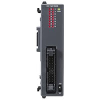
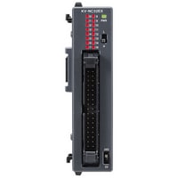
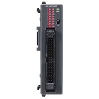
Connector type: Base unit
|
Model |
KV-NC32T |
|||
|
Image |
|
|||
|
General specifications |
Power voltage |
24 VDC (+10%/-15%) |
||
|
Operating ambient temperature |
0 to 55°C (no freezing)*1 |
|||
|
Operating ambient humidity |
5 to 95% RH (no condensation) |
|||
|
Operating environment |
As little dust and corrosive gases as possible |
|||
|
Noise immunity |
1500 V peak-to-peak or more, pulse width 1 µs, 50 ns (by noise simulator), IEC standard compliant (IEC61000-4-2/3/4/6) |
|||
|
Withstand voltage |
1500 VAC for 1 minute, between power supply terminal and I/O terminals and between all external terminals and case |
|||
|
Insulation resistance |
50 MΩ or more |
|||
|
Storage temperature |
-25 to +75°C |
|||
|
Vibration resistance |
Intermittent vibration |
Frequency: 5 to 9 Hz |
Amplitude: 3.5 mm*2*3 |
|
|
Frequency: 9 to 150 Hz |
Acceleration: 9.8 m/s2*4 |
|||
|
Continuous vibration |
Frequency: 5 to 9 Hz |
Amplitude: 1.75 mm*4 |
||
|
Frequency: 9 to 150 Hz |
Acceleration: 4.9 m/s2*4 |
|||
|
Shock resistance |
Acceleration: 150 m/s2, application time: 11 ms, two times in each of the X, Y, and Z directions |
|||
|
Operating altitude |
2000 m or less |
|||
|
Overvoltage category |
Ⅰ |
|||
|
Pollution degree |
2 |
|||
|
Performance specifications |
Calculation control method |
Programme storage method |
||
|
I/O control method |
Refresh method |
|||
|
Programming language |
Expanded ladder, KV Script, mnemonic |
|||
|
Number of instructions |
Basic instructions: 81 kinds and 182 instructions, Application instructions: 39 kinds and 56 instructions |
|||
|
Instruction execution speed |
Basic instruction: 50 ns minimum, Application instruction: 170 ns minimum |
|||
|
Program capacity |
32k steps |
|||
|
Maximum number of attachable I/O units |
8 |
|||
|
Maximum number of I/O points |
256 (excluding the base unit I/O) |
|||
|
Input relay/Output relay/Internal auxiliary relay |
R |
Total of 9600 points 1 bit (R000 to R59915) |
||
|
Link relay |
B |
8192 points 1 bit (B0 to B1FFF) |
||
|
Internal auxiliary relay |
MR |
9600 points 1 bit (MR000 to MR59915) |
||
|
Latch relay |
LR |
3200 points 1 bit (LR000 to LR19915) |
||
|
Control relay |
CR |
1440 points 1 bit (CR000 to CR8915) |
||
|
Timer |
T |
512 points 32 bits (T0 to T511) |
||
|
Counter |
C |
256 points 32 bits (C0 to C255) |
||
|
Data memory |
DM |
32768 points 16 bits (DM0 to DM32767) |
||
|
Link register |
W |
16384 points 16 bits (W0 to W3FFF) |
||
|
Temporary memory |
TM |
512 points 16 bits (TM0 to TM511) |
||
|
High-speed counter |
CTH |
3 points (CTH0 to CTH2) |
||
|
High-speed |
CTC |
6 points (CTC0 to CTC5) |
||
|
Index register |
Z |
12 points 32 bits (Z01 to Z12) |
||
|
Control memory |
CM |
9000 points 16 bits (CM0 to CM8999) |
||
|
Positioning pulse output |
3 axes |
|||
|
Base unit I/O |
Input: 16 points, output: 16 points |
|||
|
Number of comments and |
Device comment |
20000 |
||
|
Label |
28000 |
|||
|
Power off hold function |
Programme memory |
Flash ROM can be rewritten 10000 times |
||
|
Device |
Nonvolatile RAM*7 |
|||
|
Clock function |
±60 seconds/month (at 25°C) |
|||
|
Self-diagnosis function |
CPU error, RAM error, and other problems |
|||
|
Input specifications |
Relay number |
General input: R000 to R009 (10 points), High-speed A-phase and B-phase input: R010 to R015 (6 points) |
||
|
Input mode |
24 VDC input (open collector) |
|||
|
Maximum input voltage |
26.4 VDC |
|||
|
Rated input voltage |
24 VDC (General input: 5.3 mA, High-speed A-phase and B-phase input: 6.5 mA*8) |
|||
|
Minimum ON voltage |
19 VDC |
|||
|
Maximum OFF current |
1.5 mA |
|||
|
Common method |
All points/1 common (1 terminal) |
|||
|
Circuit delay time |
General input: OFF to ON Max. 30 µs (Typ. 3.5 µs), ON to OFF Max. 50 µs (Typ. 15 µs) |
|||
|
Input time constant |
Normal: 10 ms, When the HSP instruction is used: 10 µs |
|||
|
Delay by input time constant |
||||
|
Response frequency |
(High-speed A-phase and B-phase input) Single phase: 100 kHz, phase difference: 50 kHz, 24 V±10%, Duty 50% |
|||
|
Output specifications |
Relay number |
General output: R506 to R515 (10 points), High-speed output: R500 to R505 (6 points) |
||
|
Output mode |
MOSFET (N-ch) |
|||
|
Rated load |
30 VDC |
|||
|
Maximum OFF voltage |
30 VDC |
|||
|
Leakage current at OFF |
100 µA or less |
|||
|
Residual voltage at ON |
0.6 VDC or less |
|||
|
Common method |
16 points/1 common |
|||
|
ON/OFF response time |
General output: |
|||
|
Overcurrent protection |
Protection provided for each common*10 |
|||
|
Output frequency |
High-speed output: 100 kHz (7 to 100 mA load) |
|||
|
Built-in serial port |
Interface |
Communication standard |
RS-232C |
|
|
Connection |
Modular connector |
|||
|
Transmission specifications RS-232C |
Baud rate |
1200, 2400, 4800, 9600, 19200, 38400, 57600, 115200 bps |
||
|
Transmission method |
Full duplex |
|||
|
Data format |
Start bit |
1 bit |
||
|
Data bits |
7 bits, 8 bits |
|||
|
Stop bits |
1 bit, 2 bits |
|||
|
Error detection |
Parity |
Even, odd, none |
||
|
Transmission distance |
15 m |
|||
|
Number of transmission units |
1 |
|||
|
Indication |
Common between SD/RD |
|||
|
Internal current consumption |
260 mA |
|||
|
Weight |
Approx. 220 g |
|||
|
*1 The temperature below the unit centre (30 mm) inside a control panel. |
||||

Connector type: Expansion input unit
|
Model |
KV-NC16EX |
KV-NC32EX |
KV-NC16EXE |
|||
|
Image |
|
|
|
|||
|
Expansion input unit |
External connection method |
Connector |
European terminal block |
|||
|
Input Points |
16 points |
32 points |
16 points |
|||
|
Input terminals |
24 VDC mode, 5 VDC mode |
|||||
|
Maximum input voltage |
26.4 VDC |
|||||
|
Input rated voltage |
24 VDC mode |
5.2 mA |
||||
|
5 VDC mode |
1 mA |
|||||
|
Minimum ON voltage |
24 VDC mode |
19 V |
||||
|
5 VDC mode |
3.5 V |
|||||
|
Maximum OFF voltage |
24 VDC mode |
1.5 mA |
||||
|
5 VDC mode |
1.5 V |
|||||
|
Common method |
16 points/1 common (2 terminals)*1 |
32 points/1 common (2 terminals)*1 |
16 points/1 common (16 terminals) *2 |
|||
|
Input time constant (four-level switching) |
Input time constant setting |
OFF to ON: Typ. |
25 µs: 10 µs |
|||
|
OFF to ON: Max. |
25 µs: 50 µs |
|||||
|
ON to OFF: Typ. |
25 µs: 50 µs |
|||||
|
ON to OFF: Max. |
25 µs: 150 µs |
|||||
|
Input impedance |
4.4 kΩ |
|||||
|
Internal current consumption |
20 mA or less |
|||||
|
Weight |
Approx. 100 g |
Approx. 110 g |
Approx. 120 g |
|||
|
*1 The KV-NX16EX and KV-NC32EX have 2 COM terminals, but these are shared internally. |
||||||
Connector type: Expansion ounput unit
|
Model |
KV-NC8ER |
KV-NC16ET |
KV-NC16ETP |
KV-NC32ET |
KV-NC32ETP |
KV-NC16ETE |
KV-NC16ETPE |
|||
|
Image |
|
|
|
|
|
|
|
|||
|
Expansion output unit |
External connectionmethod |
Relay |
MOSFET output (With overcurrent protection function)*2*3 |
MOSFET output (With overcurrent protection function)*7*3 |
MOSFET output (With overcurrent protection function)*2*3 |
|||||
|
External connection method |
European terminal block |
Connector |
European terminal block |
|||||||
|
Rated load |
250 VAC/30 VDC, 2 A |
30 VDC, 0.2 A*4 |
30 VDC, 0.2 A*9 |
|||||||
|
Leakage current (when output is OFF) |
― |
100 µA or less |
||||||||
|
Residual voltage (at ON) |
0.6 VDC or less |
|||||||||
|
ON resistance |
50mΩ or less |
― |
||||||||
|
Minimum applicable load |
― |
|||||||||
|
Common method |
4 points/1 common (4 terminals) *1 |
16 points/1 common (2 terminals)*5*6 |
32 points/1 common (2 terminals)*5*8 |
16 points/1 common (16 terminals)*5*6 |
||||||
|
Response time |
OFF to ON |
10 ms or less |
100 µs or less (with a load of 1 mA or more) |
|||||||
|
ON to OFF |
200 µs or less (with a load of 1 mA or more) |
|||||||||
|
Relay life |
Electrical : 100,000 cycles or more (20 cycles/minute) Mechanical : 20,000,000 cycles or more |
― |
||||||||
|
Relay replacement |
Not possible |
|||||||||
|
Internal current consumption |
70 mA or less |
30 mA or less |
50 mA or less |
30 mA or less |
||||||
|
Weight |
Approx. 130 g |
Approx. 100 g |
Approx. 110 g |
Approx. 120 g |
||||||
|
*1 The KV-NC8ER has four terminals for each of C0 and C1 respectively, which are shorted internally. (C0 and C1 are independent.) |
||||||||||
Connector type: A/D & D/A conversion unit
|
Model |
KV-NC4AD |
KV-NC2DA |
|||
|
Image |
|
|
|||
|
Conversion speed |
80 µs/channel*1 |
80µs/CH |
|||
|
Conversion |
A/D conversion |
D/A conversion |
|||
|
Points |
4 (single end) |
2 |
|||
|
Range/resolution |
Voltage |
-10 V to +10 V |
1/8000 2.5mV |
||
|
0 to 10 V |
1/4000 2.5mV |
||||
|
0 to 5 V |
1/4000 1.25mV |
||||
|
1 to 5 V |
1/3200 1.25mV |
||||
|
Current |
0 to 20 mA |
1/4000 5µA |
|||
|
4 to 20 mA |
1/3200 5µA |
||||
|
Conversion precision |
Voltage |
Without temperature |
±0.3% of F.S. (at 25°C ±5°C) |
||
|
With temperature |
±0.3% of F.S. (at 0 to 55°C) |
±0.3% of F.S. (at 25°C ±5°C) |
|||
|
Current |
Without temperature |
±0.4% of F.S. (at 25°C ±5°C) |
|||
|
With temperature |
±0.4% of F.S. (at 0 to 55°C) |
||||
|
Input resistance |
Voltage |
5MΩ |
― |
||
|
Current |
250Ω |
||||
|
Absolute maximum input |
Voltage |
±15V |
|||
|
Current |
±30mA |
||||
|
Isolation method |
Between analogue input |
Isolated (photocoupler, transformer) |
|||
|
Between analogue input channels |
Non-isolated |
||||
|
Minimum load resistance |
Voltage |
― |
1kΩ |
||
|
Maximum load resistance |
Current |
600Ω |
|||
|
Special functions |
Input range switching, |
Output range switching, output data offset, |
|||
|
*1 When the temperature fluctuation compensation is used, the temperature fluctuation compensation time of 80 µs will be added regardless of the number of channels being used. |
|||||

Connector type: Temperature input unit
|
Model |
KV-NC4TP |
|||
|
Image |
|
|||
|
Temperature input unit |
Number of inputs |
4*1 |
||
|
Input |
Thermocouple, Platinum resistance thermometer |
|||
|
Input range |
Thermocouple |
K : -270.0 to 1372.0˚C |
||
|
Platinum resistance thermometer |
Pt100 : -200.0 to 850.0˚C |
|||
|
Overall accuracy |
Thermocouple |
±0.2% of F.S. (at 25°C ±5°C) |
||
|
Platinum resistance thermometer |
||||
|
Allowable wiring resistance |
Platinum resistance thermometer |
100 Ω max./wire |
||
|
Conversion speed |
125ms/ch |
|||
|
Isolation method |
Between input terminals and base unit : |
|||
|
Special functions |
Channel skip, disconnection detection, |
|||
|
Internal current consumption |
40mA or less |
|||
|
Weight |
Approx. 110 g |
|||
|
*1 Individual setting is possible for each channel. |
||||
Connector type: EtherNet/IP™ unit
|
Model |
KV-NC1EP |
|||
|
Image |
|
|||
|
EtherNet/IP® unit (communication specifications) |
CIP service |
Cyclic |
Number of connections |
64*1 |
|
RP I (communication cycle) |
0.5 to 10000 ms (0.5 ms increments) Setting is possible for each connection. |
|||
|
Transmission trigger: Output to the adapter |
Cyclic |
|||
|
Transmission trigger: Input from the adapter |
Cyclic / Change of state*2 |
|||
|
Cyclic communication |
Tolerable communication bandwidth for cyclic communication (@504 bytes) |
6000 (pps)*3 |
||
|
Tolerable communication bandwidth for cyclic communication (@1444 bytes) |
3000 (pps)*3 |
|||
|
Cyclic |
Maximum number of refresh words |
8k words |
||
|
Maximum data size per connection |
504 bytes or 1444 bytes*4 |
|||
|
Multicast filter function |
Provided (IGMP client function)*5 |
|||
|
Message communication |
Class 3 (connection type): Server |
No. of connections : 64*6 |
||
|
UCMM (non-connection type): Client |
No. of simultaneous messages : 32 |
|||
|
UCMM (non-connection type): Server |
No. of simultaneous messages : 96 |
|||
|
EtherNet/IP® conformance test |
Conforming to CT10 |
|||
|
EtherNet/IP® unit (performance specifications) |
PC applications |
No. of sockets TCP : 8 UDP : 0 Port number : 8500 (can be set within the range between 1 and 65535)*7 |
||
|
Host link communication |
No. of sockets TCP : Total : 15 UDP : 1 Port number : 8501 (can be set within the range between 1 and 65535)*8*9 |
|||
|
MC protocol communication |
No. of sockets TCP : Total : 15 UDP : 1 Port number : 5000 (can be set within the range between 1 and 65535)*8*9*10 |
|||
|
VT3 connection |
No. of sockets TCP : 0 UDP : 1 Port number : 8502 (can be set within the range between 1 and 65535) |
|||
|
FTP server |
No. of sockets TCP : 4 Port number : 20, 21 |
|||
|
Clock data automatic adjustment |
No. of sockets UDP : 1 Port number : 123 |
|||
|
E-mail transmission (SMTP, POP3) |
No. of sockets TCP : 2 Port number : 25, 110 |
|||
|
DNS |
No. of sockets UDP : 1 Port number : 53 |
|||
|
FTP client |
No. of sockets TCP : 2 Port number : 20, 21 (can be set within the range between 1 and 65535) |
|||
|
Easy PLC link |
No. of sockets UDP : 1 Port number : 5001 (can be set within the range between 1 and 65535) |
|||
|
EtherNet/IP® cyclic communication function |
No. of sockets TCP : Total : 320 UDP : 1 Port number : 2222 |
|||
|
EtherNet/IP® message communication function |
No. of sockets TCP : Total : 320 UDP : 1 Port number : 44818 |
|||
|
Internal current consumption |
90mA or less |
|||
|
Weight |
Approx. 110 g |
|||
|
*1 The number of connection may exceed 64 where the KV-NC1EP is connected with the multicast of cyclic communication from the originator. The operation of the KV-NC1EP, however, is guaranteed up to 64 connections. |
||||
Connector type: Serial communication adapter
|
Model |
KV-NC10L |
KV-NC20L |
|||
|
Image |
|
|
|||
|
Transmission |
Electrical termination (Terminator) |
Set with the switch on the front panel of the main unit |
|||
|
Baud rate |
1200,2400,4800,9600,19200,38400,57600,115200bps |
||||
|
Transmission method |
Full duplex |
Port 1 : Full duplex |
|||
|
Data format |
Start bit |
1 bit |
|||
|
Data bits |
7 bit, 8 bit |
||||
|
Stop bits |
1 bit, 2 bit |
||||
|
Error detection |
Parity |
Even, odd, none |
|||
|
RS/CS flow control |
Enabled, disabled |
Port1 : Enabled, disabled |
|||
|
Interface |
Communication standard |
RS-232C |
Port 1 : RS-232C |
||
|
Connection |
D-sub 9-pin |
Port 1 : D-sub 9-pin |
|||
|
Transmission |
Transmission distance |
15m |
Port1 : 15 m |
||
|
Number of transmission units |
1 |
Port1 : 1 |
|||
|
Indication |
SD (orange), RD (orange) |
||||
|
Weight |
Approx. 100 g |
Approx. 110 g |
|||

|
Model |
KV-EP02 |
|||
|
Image |
|
|||
|
General specifications |
Power voltage |
24 VDC (+10% / -15 %) |
||
|
Operating ambient temperature |
0 to +55°C (no freezing)*1*2 |
|||
|
Operating ambient humidity |
5 to 95 % RH (no condensation)*1 |
|||
|
Ambient temperature for storage |
-25 to +75°C |
|||
|
Storage relative humidity |
5 to 95 % RH (no condensation)*1 |
|||
|
Operating environment |
No dust or corrosive gas |
|||
|
Altitude |
2,000 m or less |
|||
|
Noise immunity |
1,500 Vp-p or more; pulse width: 1 µs, 50 ns (based on noise simulator); |
|||
|
Withstand voltage |
1,500 VAC for 1 minute between the power terminals and the I/O terminals, and between the external terminals and the housing |
|||
|
Insulation resistance |
50 MΩ or more (between the power terminals and the input terminals and between the external terminals and the housing, with 500 VDC megohmmeter) |
|||
|
Vibration resistance |
Intermittent vibration |
Frequency 5 to 9 Hz |
When mounted on a DIN rail: Half amplitude: 3.5 mm*3 |
|
|
Frequency 9 to 150 Hz |
When mounted on a DIN rail: Acceleration: 9.8 m/s2*3 |
|||
|
Continuous vibration |
Frequency 5 to 9 Hz |
When mounted on a DIN rail: Half amplitude: 1.75 mm*3 |
||
|
Frequency 9 to 150 Hz |
When mounted on a DIN rail: Acceleration: 4.9 m/s2*3 |
|||
|
Internal current consumption (excluding current for driving input circuits) |
120 mA or less*4 |
|||
|
Shock resistance |
When mounted on a DIN rail: Acceleration: 150 m/s2; operation time: 11 ms; 3 times in each of the X, Y, and Z directions |
|||
|
Overvoltage category |
I |
|||
|
Pollution degree |
2 |
|||
|
Weight |
Approx. 130 g |
|||
|
Performance specifications |
Connection interface |
RJ-45 8-position modular connector x 2 ports |
||
|
Transmission rate |
10BASE-T: 10 Mbps, 100BASE-TX: 100 Mbps*5 |
|||
|
Transmission media |
10BASE-T: Category 3 or higher UTP or STP (STP is recommended) |
|||
|
Maximum number of connectable hubs |
10BASE-T: 4, 100BASE-TX: 2*7 |
|||
|
Maximum cable length |
100 m*8 |
|||
|
EtherNet/IP®specifications |
Trigger |
Cyclic |
||
|
Supported functions |
Cyclic communication,Message communication (explicit message communication),UCMM, and Class 3 support |
|||
|
Number of connections |
64 |
|||
|
RPI (communication cycle) |
0.5 to 10,000 ms (0.5 ms unit) |
|||
|
Conformance test |
Compliant with CT14 |
|||
|
*1 Guaranteed range in which the system can be used. |
||||
