
Programmable Logic Controller
KV Nano series
Base unit: DC power supply type, Input 14 points/output 10 points, Transistor (source) output KV-N24DTP
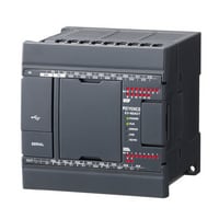
*Please note that accessories depicted in the image are for illustrative purposes only and may not be included with the product.

Specifications
Model | KV-N24DTP | |||
General specifications | Power voltage | 24 VDC (+10%/-15%) | ||
Operating ambient temperature | 0 to 55°C (no freezing)*1*2 | |||
Operating ambient humidity | 5 to 95% RH (no condensation)*1 | |||
Operating environment | As little dust and corrosive gases as possible | |||
Noise immunity | 1500 V peak-to-peak or more, pulse width 1 µs, 50 ns (by noise simulator), IEC standard compliant (IEC61000-4-2/3/4/6) | |||
Withstand voltage | 1500 VAC for 1 minute, between power supply terminal and I/O terminals and between all external terminals and case | |||
Insulation resistance | 50 MΩ or more | |||
Output power supply voltage | - | |||
Storage temperature | -25 to +75°C | |||
Vibration resistance | Intermittent vibration | Frequency: 5 to 9 Hz | Amplitude: 3.5 mm*3*4 | |
Frequency: 9 to 150 Hz | Acceleration: 9.8 m/s2*3*5 | |||
Continuous vibration | Frequency: 5 to 9 Hz | Amplitude: 1.75 mm*3*5 | ||
Frequency: 9 to 150 Hz | Acceleration: 4.9 m/s2*3*5 | |||
Shock resistance | Acceleration: 150 m/s2, application time: 11 ms, two times in each of the X, Y, and Z directions | |||
Operating altitude | 2000 m or less | |||
Overvoltage category | AC: II, DC: I | |||
Pollution degree | 2 | |||
Performance specifications | Calculation control method | Programme storage method | ||
I/O control method | Refresh method | |||
Programming language | Expanded ladder, KV Script, mnemonic | |||
Number of instructions | Basic instructions: 81 kinds and 182 instructions, Application instructions: 39 kinds and 56 instructions | |||
Instruction execution speed | Basic instruction: 50 ns minimum, Application instruction: 170 ns minimum | |||
Program capacity | 8k steps | |||
Maximum number of attachable I/O units | 8 | |||
Maximum number of I/O points | 256 (excluding the base unit I/O) | |||
Input relay/Output relay/Internal auxiliary relay | R | Total of 9600 points 1 bit (R000 to R59915) | ||
Link relay | B | 8192 points 1 bit (B0 to B1FFF) | ||
Internal auxiliary relay | MR | 9600 points 1 bit (MR000 to MR59915) | ||
Latch relay | LR | 3200 points 1 bit (LR000 to LR19915) | ||
Control relay | CR | 1440 points 1 bit (CR000 to CR8915) | ||
Timer | T | 512 points 32 bits (T0 to T511) | ||
Counter | C | 256 points 32 bits (C0 to C255) | ||
Data memory | DM | 32768 points 16 bits (DM0 to DM32767) | ||
Link register | W | 16384 points 16 bits (W0 to W3FFF) | ||
Temporary memory | TM | 512 points 16 bits (TM0 to TM511) | ||
High-speed counter | CTH | 2 points (CTH0 and CTH1) | ||
High-speed | CTC | 4 points (CTC0 to CTC3) | ||
Index register | Z | 12 points 32 bits (Z01 to Z12) | ||
Control memory | CM | 9000 points 16 bits (CM0 to CM8999) | ||
Positioning pulse output | 2 axes | |||
Base unit I/O | Input: 14 points; output: 10 points | |||
Number of comments and | Device comment | 20000 | ||
Label | 28000 | |||
Power off hold function | Programme memory | Flash ROM can be rewritten 10000 times | ||
Device | Nonvolatile RAM*8 | |||
Self-diagnosis function | CPU error, RAM error, and other problems | |||
Input specifications | Relay number | General input: R000 to R003, R008 to R013 (10 points) | ||
Input mode | 24 VDC input (open collector) | |||
Maximum input voltage | 26.4 VDC | |||
Rated input voltage | 24 VDC (General input: 5.3 mA, High-speed A-phase and B-phase input: 6.5 mA*9) | |||
Minimum ON voltage | 19 VDC | |||
Maximum OFF current | 1.5 mA | |||
Common method | General input: All inputs/common (1 terminal) | |||
Circuit delay time | General input: | |||
Input time constant | Normal: 10 ms, When the HSP instruction is used: 10 µs | |||
Delay by input time constant | ||||
Response frequency | (High-speed A-phase and B-phase input) Single phase: 100 kHz, phase difference: 50 kHz, 24 V±10%, Duty 50% | |||
Output specifications | Relay number | General output: R504 to R509 (6 points), High-speed output: R500 to R503 (4 points) | ||
Output mode | Source output type | |||
Rated load | 30 VDC, 0.5 A | |||
Maximum OFF voltage | 30 VDC | |||
Leakage current at OFF | 100 µA or less | |||
Residual voltage at ON | 0.8 VDC or less (with 0.5 A output), 0.6 VDC or less (with 0.3 A output) | |||
Common method | 8 to 10 points/1 common | |||
ON/OFF response time | General output: | |||
Overcurrent protection | Protection provided for each common*11 | |||
Output frequency | High-speed output: 100 kHz (7 to 100 mA load) | |||
Built-in serial port | Interface | Communication standard | RS-232C | |
Connection | Modular connector | |||
Transmission specifications RS-232C | Baud rate | 1200, 2400, 4800, 9600, 19200, 38400, 57600, 115200 bps | ||
Transmission method | Full duplex | |||
Data format | Start bit | 1 bit | ||
Data bits | 7 bits, 8 bits | |||
Stop bits | 1 bit, 2 bits | |||
Error detection | Parity | Even, odd, none | ||
Transmission distance | 15 m | |||
Number of transmission units | 1 | |||
Indication | SD (green), RD (red) | |||
Internal current consumption | 160 mA | |||
Weight | Approx. 390 g | |||
*1 The range guaranteed as a system (excluding items specially noted for the units and cassettes). | ||||