Programmable Logic Controller
KV-8000 series
Specs Programmable Logic Controller KV-8000 series
CPU unit
|
Model |
KV-8000 |
|||
|
Image |
|
|||
|
General specifications |
Power voltage |
System configuration using an expansion unit for KV-5000/3000 Series: |
||
|
Operating ambient temperature |
System configuration using an expansion unit for KV-5000/3000 Series: |
|||
|
Operating ambient humidity |
System configuration using an expansion unit for KV-5000/3000 Series: |
|||
|
Ambient temperature for storage |
System configuration using an expansion unit for KV-5000/3000 Series: |
|||
|
Storage relative humidity |
System configuration using an expansion unit for KV-5000/3000 Series: |
|||
|
Operating environment |
No dust or corrosive gas |
|||
|
Altitude |
2000 m or less |
|||
|
Noise immunity |
1500 Vp-p or more; |
|||
|
Withstand voltage |
1500 VAC for one minute |
|||
|
Insulation resistance |
50 MΩ or more |
|||
|
Vibration resistance |
Intermittent vibration |
Frequency 5 to 9 Hz |
Half amplitude: 3.5 mm*3 |
|
|
Frequency 9 to 150 Hz |
Acceleration: 9.8 m/s2*3 |
|||
|
Continuous vibration |
Frequency 5 to 9 Hz |
Half amplitude: 1.75 mm*3 |
||
|
Frequency 9 to 150 Hz |
Acceleration: 4.9 m/s2*3 |
|||
|
Internal current consumption (excluding current for driving input circuits) |
400 mA or less*4 |
|||
|
Shock resistance |
Acceleration: 150 m/s2, Application time: 11 ms, |
|||
|
Overvoltage category |
I (II when using KV-PU1) |
|||
|
Pollution degree |
2 |
|||
|
Weight |
KV-8000: Approx. 340 g, |
|||
|
Performance specifications |
Calculation control method |
Program storage method |
||
|
I/O control method |
Refresh method |
|||
|
Programming language |
Expanded ladder, KV Script, mnemonic |
|||
|
Number of commands |
Basic instruction: 80 classes, 181 instructions |
|||
|
Instruction execution speed |
Basic instruction: Min. 0.96 ns |
|||
|
CPU memory capacity |
64 MB |
|||
|
Program capacity |
Approx. 1500 k steps |
|||
|
Maximum number of units to be installed |
16 units (KV-8000/7000 Series expansion unit only), |
|||
|
Maximum number of I/O points |
Maximum 3072 points for expansion |
|||
|
Bit device |
Input relay R |
Total 32000 points 1 bit |
||
|
Output relay R |
||||
|
Internal auxiliary relay R |
||||
|
Self-diagnosis function |
CPU error, RAM error, and other problems |
|||
|
Bit device |
Link relay B |
32768 points 1 bit |
||
|
Internal auxiliary relay MR |
64000 points 1 bit |
|||
|
Latch relay LR |
16000 points 1 bit |
|||
|
Control relay CR |
1280 points 1 bit |
|||
|
Word device |
Timer T |
4000 points 32 bits |
||
|
Counter C |
||||
|
Data memory DM |
65535 points 16 bits |
|||
|
Expansion data memory EM |
||||
|
File register |
Current bank FM |
524288 points 16 bits |
||
|
Dial mode ZF |
||||
|
Link register W |
32768 points 16 bits |
|||
|
Temporary memory TM |
512 points 16 bits |
|||
|
Index register Z |
12 points 32 bits |
|||
|
Control memory CM |
7600 points 16 bits |
|||
|
Number of comments/ labels stored in main unit |
Device comment |
Approx. 224000 |
||
|
Label |
Approx. 285000 |
|||
|
Power off hold function |
Program memory |
Flash ROM can be written 10000 times |
||
|
Device |
Nonvolatile RAM |
|||
|
Calendar clock |
Backup capacitor lasts approx. 15 days (at 25°C) |
|||
|
*1 Guaranteed range in which the system can be used. |
||||

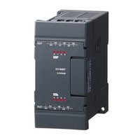
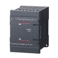
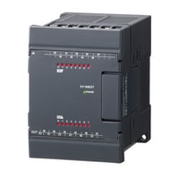
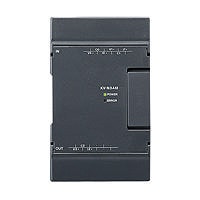
Input unit
|
Model |
KV-B16XC |
KV-C32XC |
KV-C64XC |
|||
|
Image |
|
|
|
|||
|
Type |
Input unit |
|||||
|
External connection mode |
Removable terminal block |
Connector (MIL specification)*3 |
||||
|
Input |
Number of inputs |
16 points |
32 points |
64 points |
||
|
Input mode |
24 VDC mode, 5 VDC mode |
24 VDC mode*4 |
||||
|
Max. input voltage |
26.4 VDC |
|||||
|
Rated input voltage |
24 VDC mode: 24 VDC 5.3 mA, 5 VDC mode: 5 VDC 1 mA |
24 VDC 4.1 mA |
||||
|
Min. ON voltage |
24 VDC mode: 19 V, 5 VDC mode: 3.5 V |
19 V |
||||
|
Max. OFF current |
24 VDC mode: 1.5 mA |
1.5 mA |
||||
|
Max. OFF voltage |
5 VDC mode: 1.5 V |
- |
||||
|
Common point mode |
16 points/1 common point (2 terminals)*1 |
32 points/1 common point (2 terminals)*1 |
32 points/1 common point (4 terminals)*5 |
|||
|
Input time constant |
[Input time constant setting 25 µs] OFF to ON: TYP 25 µs/MAX 65 µs, ON to OFF: TYP 75 µs/MAX 120 µs |
|||||
|
Input impedance |
4.3 kΩ |
5.6 kΩ |
||||
|
Internal current consumption |
15 mA or less |
25 mA or less |
||||
|
Weight |
Approx. 120 g |
Approx. 110 g |
Approx. 140 g |
|||
|
*1 Even though KV-B16XC and KV-C32XC have two common points, they are the same internally. |
||||||
Output unit
|
Model |
KV-B16TCP |
KV-C32TCP |
KV-C64TCP |
|||
|
Image |
|
|
|
|||
|
Type |
Output unit |
|||||
|
External connection mode |
Removable terminal block |
Connector (MIL specification)*2 |
||||
|
Output |
Number of outputs |
16 points |
32 points |
64 points |
||
|
Output form |
Transistor (source) |
|||||
|
Rated load |
30 VDC 0.2 A |
|||||
|
Leak current at OFF |
100 µA or less |
|||||
|
Residual voltage at ON |
0.5 V or less |
|||||
|
ON resistance |
- |
|||||
|
Common point mode |
16 points/1 common point (2 terminals)*1 |
32 points/1 common point (2 terminals)*1 |
64 points/1 common point (4 terminals)*3 |
|||
|
Operating time |
OFF to ON: 10 µs or less、ON to OFF: 200 µs or less |
OFF to ON: 50 µs or less、ON to OFF: 200 µs or less |
||||
|
Internal current consumption |
35 mA or less |
55 mA or less |
100 mA or less |
|||
|
Weight |
Approx. 130 g |
Approx. 100 g |
Approx. 140 g |
|||
|
*1 Although KV-B16TD, KV-C32TD, KV-B16TCP, and KV-C32TCP have two points, they are the same internally. |
||||||
Output unit
|
Model |
KV-B8RC |
KV-B16RC |
KV-B16TD |
KV-C32TD |
KV-C64TD |
|||
|
Image |
|
|
|
|
|
|||
|
Type |
Output unit |
|||||||
|
External connection mode |
Removable terminal block |
Connector (MIL specification)*2 |
||||||
|
Output |
Number of outputs |
8 points |
16 points |
32 points |
64 points |
|||
|
Output form |
Relay |
MOS-FET (sink) (with overcurrentprevention function) |
||||||
|
Rated load |
250 VAC/30 VDC 2 A |
250 VAC/30 VDC 2 A (8 A/1 common point) |
30 VDC 0.3 A |
30 VDC 0.2 A |
||||
|
Leak current at OFF |
- |
100 µA or less |
||||||
|
Residual voltage at ON |
0.5 V or less |
|||||||
|
ON resistance |
50 mΩ or less |
- |
||||||
|
Common point mode |
Independent |
8 points/1 common points |
16 points/1 common point (2 terminals)*1 |
32 points/1 common point (2 terminals)*1 |
64 points/1 common point (4 terminals)*3 |
|||
|
Operating time |
OFF to ON/ON to OFF: 10 ms or less |
OFF to ON: 100 µs or less、ON to OFF: 300 µs or less |
OFF to ON: 150 µs or less、ON to OFF: 300 µs or less |
|||||
|
Internal current consumption |
65 mA or less |
120 mA or less |
45 mA or less |
65 mA or less |
120 mA or less |
|||
|
Weight |
Approx. 160 g |
Approx. 190 g |
Approx. 130 g |
Approx. 100 g |
Approx. 140 g |
|||
|
*1 Although KV-B16TD, KV-C32TD, KV-B16TCP, and KV-C32TCP have two points, they are the same internally. |
||||||||

I/O unit
|
Model |
KV-B8XTD |
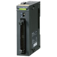
KV-C16XTD |
KV-C32XTD |
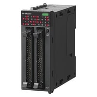
KV-SIR32XT*5 |
|||
|
Image |
|
|
|
|
|||
|
Type |
I/O unit |
High-speed I/O unit |
|||||
|
External connection mode |
Removable terminal block |
Connector (MIL standard)*2 |
|||||
|
Input |
Number of inputs |
8 points |
16 points |
32 points |
|||
|
Input mode |
24 VDC mode, 5 VDC mode |
24 VDC mode*3 |
24 VDC mode, 5 VDC mode*6 (Overvoltage protection function included*7) |
||||
|
Max. input voltage |
26.4 VDC |
24 VDC mode: 28.8 VDC, 5 VDC mode: 6.0 VDC |
|||||
|
Rated input voltage |
24 VDC mode: 24 VDC 5.3 mA, 5 VDC mode: 5 VDC 1 mA |
24 VDC 4.1 mA |
24 VDC mode: 24 VDC 5.1 mA, 5 VDC mode: 5 VDC 8.8 mA |
||||
|
Min. ON voltage |
24 VDC mode: 19 V, 5 VDC mode: 3.5 V |
19 V |
24 VDC mode: 19 V, 5 VDC mode: 3.5 V |
||||
|
Max. OFF current |
24 VDC mode: 1.5 mA |
1.5 mA |
24 VDC mode: 1.5 mA |
||||
|
Max. OFF voltage |
5 VDC mode: 1.5 V |
- |
5 VDC mode: 1.5 V |
||||
|
Common point mode |
8 points/1 common point (1 terminal) |
16 points/1 common point (1 terminal) |
32 points/1 common point (2 terminals)*4 |
16 points/1 common point (2 terminals)*8 |
|||
|
Input time constant |
25 µs/300 µs*1/1 ms/10 ms |
1 µs/10 µs/20 µs/100 µs/500 µs/1 ms/5 ms/10 ms/50 ms |
|||||
|
Input impedance |
4.3 kΩ |
5.6 kΩ |
24 VDC mode: 4.4 kΩ, 5 VDC mode: 350 Ω |
||||
|
Output |
Number of outputs |
8 points |
16 points |
32 points |
|||
|
Output form |
MOS-FET (N ch) (with an overcurrent-proof function) |
MOSFET (N-ch) (with overcurrent protection function)*9 |
|||||
|
Rated load |
30 VDC 0.3 A |
30 VDC 0.2 A |
30 VDC 0.2 A (1.6 A/1 common point) |
||||
|
Leak current at OFF |
100 µA or less |
||||||
|
Residual voltage at ON |
0.5 V or less |
0.5 VDC or less |
|||||
|
Common point mode |
8 points/1 common point (1 terminal) |
16 points/1 common point (1 terminal) |
32 points/1 common point (2 terminals)*4 |
16 points/1 common point (2 terminals)*8 |
|||
|
Operating time |
OFF to ON: 100 µs or less, ON to OFF: 300 µs or less |
OFF to ON: 150 µs or less, ON to OFF: 300 µs or less |
OFF to ON: 1 µs or less (Load: 5 mA to 200 mA) |
||||
|
Internal current consumption |
30 mA or less |
40 mA or less |
65 mA or less |
130 mA or less |
|||
|
Weight |
Approx. 130 g |
Approx. 110 g |
Approx. 130 g |
Approx. 190 g |
|||
|
*1 Setup is only possible when KV-7500/7300/5500/5000/3000 is connected. When KV-1000/700 is connected, selection is not possible. |
|||||||

High-speed analogue input unit
|
Model |
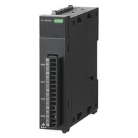
KV-SAD04*1 |
|||
|
Image |
|
|||
|
Type |
High-speed analogue input unit |
|||
|
Analogue input point |
4 points (differential input) |
|||
|
Analogue input range (resolution) |
Voltage |
-10 to +10 V (0.5 mV 1/40,000) |
||
|
Input current |
0 to 20 mA (1 µA 1/20,000) |
|||
|
Input impedance |
Voltage: 1 MΩ, Current: 250 Ω |
|||
|
Conversion speed |
10 µs/ch |
|||
|
Conversion precision |
25 °C ±5 °C: ±0.1 % (±20 digit) |
|||
|
Insulation mode |
Between unit and CPU: Photocoupler insulation, non-insulation between channels |
|||
|
Absolute max. input |
Voltage: -15 V to +35 V, Current: 30 mA |
|||
|
Internal current consumption |
80 mA or less |
|||
|
Weight |
Approx. 130 g |
|||
|
*1 For KV-8000/KV-7000 Series |
||||
High-speed analogue output unit
|
Model |
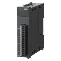
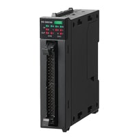
KV-SDA04*1 |
|||
|
Image |
|
|||
|
Type |
High-speed analogue output unit |
|||
|
Analogue output points |
4 points |
|||
|
Analogue output range (resolution) |
Voltage |
-10 to +10 V (0.5 mV 1/40,000) |
||
|
Input current |
0 to 20 mA (1 µA 1/20,000) |
|||
|
Conversion speed |
10 µs/ch |
|||
|
Conversion precision |
25 °C ±5 °C: ±0.1 % (±20 digit) |
|||
|
Insulation mode |
Between unit and CPU: Photocoupler insulation, non-insulation between channels |
|||
|
Min. load resistance |
Voltage: 1 kΩ |
|||
|
Max. load resistance |
Current: 500 Ω |
|||
|
Internal current consumption |
170 mA or less |
|||
|
Weight |
Approx. 140 g |
|||
|
*1 For KV-8000/KV-7000 Series |
||||
A/D and D/A conversion unit
|
Model |
KV-AM40V |
|||
|
Image |
|
|||
|
Type |
A/D and D/A conversion unit |
|||
|
Analogue I/O point |
Input: 2 points (differential input), Output: 2 points |
|||
|
Analogue I/O range (resolution) |
Voltage |
-10 to +10 V (1.25 mV 1/16,000) |
||
|
Input current |
0 to 20 mA (2.5 µA 1/8,000) |
|||
|
Input resistance |
Voltage: 5 MΩ, Current: 250 Ω |
|||
|
Conversion speed |
80 µs/ch*2*3 |
|||
|
Conversion precision |
±0.2 % of F.S. (25 °C ±5 °C), ±0.4 % of F.S. (0 to 50 °C)*4 |
|||
|
Insulation mode |
Between unit and CPU: Photocoupler insulation, Among channels: Not insulated |
|||
|
Absolute max. input |
Voltage: ±15 V, Current: 30 mA |
|||
|
Min. load resistance |
Voltage: 1 kΩ |
|||
|
Max. load resistance |
Current: 600 Ω |
|||
|
Internal current consumption |
140 mA or less |
|||
|
Weight |
Approx. 150 g |
|||
|
*1 Analogue output is not available within the range of -5 to +5 V. |
||||
Multi-input PID temperature control unit
|
Model |
KV-TF40 |
|||
|
Image |
|
|||
|
Type |
Multi-input PID temperature control unit |
|||
|
Memory elements |
EEPROM rewritable one million times |
|||
|
Number of temperature input points |
4 ch |
|||
|
Input |
Thermocouple/Platinum temperature measuring resistor*1 |
|||
|
Temperature sensor types |
Thermocouple: K, J, T, E, R, B, N, S, W5Re/W26Re |
|||
|
Indicated accuracy |
±0.3 % of F.S. ±1 digit (+25 °C), ±0.7 % of F.S. ±1 digit (0 to +50 °C) |
|||
|
Cold junction correction precision |
±1 °C |
|||
|
Sampling period |
125 ms/ch (500 ms/4 ch) |
|||
|
Control period |
1 to 100 sec. |
|||
|
Operating mode |
PID control (with auto-tuning and 3 mode stabiliser function installed) |
|||
|
Tuning mode |
PID auto-tuning mode |
|||
|
Control output |
transistor (sink) |
|||
|
Alarm output |
transistor (sink)*2 |
|||
|
Alarm mode |
Absolute value upper limit, absolute value lower limit, deviation upper limit, deviation lower limit, |
|||
|
Output |
Rated load |
30 VDC 100 mA or less |
||
|
Leak current at OFF |
100 µA or less |
|||
|
Residual voltage at ON |
1.5 V or less |
|||
|
Current sensor (CT) input |
4 ch*4 |
|||
|
Current measurement precision |
Larger of ±5 % of an input value and ±2 A of an input value |
|||
|
Insulation mode |
Between inputs and outputs: Photocoupler and transformer insulation, |
|||
|
Other functions |
Heater wire breaking alarm, control loop wire breaking alarm, measured value bias, |
|||
|
Internal current consumption |
210 mA or less |
|||
|
Weight |
Approx. 270 g |
|||
|
*1 Can be set for each channel. |
||||
Temperature and analogue multi-input unit
|
Model |
KV-TP40 |
|||
|
Image |
|
|||
|
Type |
Temperature and analogue multi-input unit |
|||
|
Number of temperature input points |
4 ch |
|||
|
Input |
Thermocouple/Platinum temperature measuring resistor/Voltage and current |
|||
|
Input range |
Thermocouple |
K: -270.0 to 1,372.0 °C |
||
|
Platinum temperature measuring resistor |
Pt100: -200.0 to 850.0 °C |
|||
|
Voltage and current |
Voltage: |
|||
|
Indicated accuracy |
±0.2 % of F.S. (25 ±5 °C), ±0.4 % of F.S. (0 to 50 °C) |
|||
|
Cold junction correction precision |
±1 °C (during thermocouple input) |
|||
|
Input resistance |
Voltage: 1 MΩ, Current: 250 Ω |
|||
|
Conversion speed |
50 ms/4 ch |
|||
|
Insulation mode |
Between an input terminal and CPU: Photocoupler transformer insulation, |
|||
|
Other functions |
External cold junction correction, wire-breaking detection function, scaling function, |
|||
|
Internal current consumption |
90 mA or less |
|||
|
Weight |
Approx. 190 g |
|||
Positioning/Motion unit
|
Model |
KV-XH16ML*1 |
KV-XH04ML*1 |
|||
|
Image |
|
|
|||
|
Type |
Positioning/Motion unit |
||||
|
Number of control axes |
16 axes (total including a virtual axis) |
4 axes (total including a virtual axis) |
|||
|
Built-in device |
Relay: 2,112 points (132 ch), data memory: 4 words |
Relay: 576 points (36 ch), data memory: 4 words |
|||
|
Output format |
MECHATROLINK-III |
||||
|
Connectable CPU units |
KV-8000/KV-7500/KV-7300 |
||||
|
Refreshes |
Automatic refresh, direct refresh, inter-unit synchronisation refresh |
||||
|
Control mode |
Position control, Torque control, Speed control, ML-III command, I/O control |
||||
|
Control period |
From 62.5 µs (from 125 µs when using the SV2 Series) |
From 500 µs |
|||
|
Starting time |
125 µs |
500 µs |
|||
|
Axis control function execution method |
Ladder program, unit program (flow, C language) |
Ladder program, unit program (flow) |
|||
|
Unit program capacity |
3 MB (max. number of blocks: approx. 20,000) |
||||
|
Flow |
Block Type |
Positioning control block, synchronisation control block, speed control block, torque control block,origin return block, current coordinate change block, speed change block, target coordinate change block,continuous positioning start block, continuous point number block, continuous independent/linearinterpolation block, continuous arc interpolation block, continuous positioning completion standby block,calculation block, standby block, program execution block, program stop/restart block,program forced end block, unit interrupt block, cam data reading/writing block, selection branch block,parallel branch block, merge block, GOTO block, start block, end block |
|||
|
Maximum number of flows |
256 |
||||
|
Number of simultaneous activities |
Unlimited |
||||
|
Internal data memory |
524,288 words |
||||
|
Position unit |
mm, deg (angle), PLS (pulse count), decimal place 0 to 9, unit conversion function available |
||||
|
Cumulative address |
-2,147,483,648 to +2,147,483,647 instruction units |
||||
|
Positioning control |
Positioning mode |
Absolute value/relative value |
|||
|
Position setting range |
-2,147,483,648 to +2,147,483,647 instruction units |
||||
|
Interpolation |
Linear interpolation (up to 16 axes), arc interpolation, helical interpolation |
||||
|
Single operation address |
-2,147,483,648 to +2,147,483,647 instruction units |
||||
|
Acceleration/deceleration curve |
Straight-line, SIN |
||||
|
Acceleration/deceleration time |
0 to 65,535 ms |
||||
|
M-code |
1 to 65,000, WITH/AFTER mode |
||||
|
Sensor positioning |
External input-based switching control from speed to position |
||||
|
Number of points |
100 points/axis (Trace control of 100 points or more using flows is also possible.) |
||||
|
Special functions |
Sync type follow-up control, absolute position follow-up control |
||||
|
Synchronisation control |
Input |
External reference, instruction coordinates, current coordinates |
|||
|
Input filter |
Reverse rotation protection function |
||||
|
Clutch |
Select from direct, slide, and following |
||||
|
Cam |
Resolution: 2,048 to 32,768, amount of data: 4 to 64 (number changes according to the resolution) |
||||
|
Correction during operation |
Correction via auxiliary input, phase correction, and lead angle correction |
||||
|
Origin return |
Origin return method |
Data set type, Dog type (push), Dog type ("With Z phase" or "Without Z phase" can be selected), |
|||
|
JOG/inching |
JOG (high speed/low speed), inching (number of pulses can be specified) |
||||
|
Teaching |
Current coordinate teaching |
||||
|
Memory data |
Point parameters (each axis), synchronisation parameters (each axis), cam data, unit program, |
||||
|
Output display |
LINK, CONNECT, error status |
||||
|
Self-diagnosis function |
Diagnosis can be made through hardware error, various parameter errors, error number, and messages |
||||
|
Parameter setting |
Parameters can be set from KV STUDIO, ladder programs, and unit programs |
||||
|
Data backup |
Coordinates: Nonvolatile memory backup (unlimited) |
||||
|
Internal current consumption |
400 mA or less |
160 mA or less |
|||
|
Weight |
Approx. 280 g |
Approx. 190 g |
|||
|
*1 For KV-8000/KV-7000 Series |
|||||

High-speed positioning unit
|
Model |
KV-SH04PL*1 |
|||
|
Image |
|
|||
|
Type |
High-speed positioning unit |
|||
|
Number of control axes |
4 axes |
|||
|
Input |
Positive (negative) direction limit switch, origin sensor, stop sensor, continuous instant starting, 1 point per axis for 4 points in total, 24 VDC input possible |
|||
|
Output |
Pulse output (differential line driver): equivalent to AM26C31 (max. 20 mA) |
|||
|
Output frequency |
1 Hz to 8 MHz |
|||
|
Output format |
Differential line driver/open collector (switched per axis via hardware switch) |
|||
|
Control mode |
Standard mode, High-speed mode |
|||
|
Control period |
Standard mode: 500 µs, High-speed mode: 62.5 µs |
|||
|
Starting time |
Standard mode: From 500 µs, High-speed mode: From 8 µs (continuous instant starting: 1 µs) |
|||
|
Basic operation |
Standard mode: Origin return/JOG, straight-line interpolation (2 to 4 axes), position control (ABS/INC), speed control (+/- direction) |
|||
|
Functions |
Standard mode: |
|||
|
Position unit |
Standard mode: mm, deg (angle), PLS (pulse count) decimal place 0 to 9, unit conversion function |
|||
|
Positioning control |
Position setting range |
-2,147,483,648 to 2,147,483,647 |
||
|
Acceleration/deceleration curve |
Standard mode: Straight-line, SIN, High-speed mode: Straight-line |
|||
|
Acceleration/deceleration rate |
Acceleration/deceleration individual setting |
|||
|
Acceleration/deceleration time |
Standard mode: 0 to 65,535 ms |
|||
|
M-code |
0 to 65,000, WITH/AFTER mode |
|||
|
Number of points |
100 points/axis |
|||
|
Origin return |
Origin return method |
Dog type ("With Z phase" or "Without Z phase" can be selected by pushing the button), Dog type inching ("With Z phase" or "Without Z phase)*2, |
||
|
JOG/inching |
Inching (number of pulses can be specified)*2, JOG |
|||
|
Teaching |
Current coordinate teaching |
|||
|
24 V power input (I/O) |
24 VDC (-15 %/+20 %) |
|||
|
5-V power output |
5 VDC (±10 %), 200 mA or less |
|||
|
Other functions |
Multi-axis simultaneous starting based on unit interrupt/inter-unit synchronisation |
|||
|
Internal current consumption |
200 mA or less, external I/O: 260 mA or less |
|||
|
Weight |
Approx. 230 g |
|||
|
*1 For KV-8000/KV-7000 Series |
||||

High-speed counter unit
|
Model |
KV-SSC02*1 |
|||
|
Image |
|
|||
|
Type |
High-speed counter unit |
|||
|
Input frequency |
4 MHz (16 MHz during 2-phase, 4 times multiplication) |
|||
|
Counting range |
32 bits |
|||
|
Number of channels |
2 ch |
|||
|
Mode |
Input selection |
External terminal (CH0, CH1), internal clock (0.05 µs, 1 µs, 10 µs, 100 µs), other CH coincidence output, |
||
|
Input mode |
1-pulse with/without direction, 2-pulse addition/subtraction operation, 2-phase 1X/2X/4X |
|||
|
Counting operation mode |
Up-down counting mode, Enable counting mode, Preset counting mode, |
|||
|
Counting mode |
Linear, ring |
|||
|
Frequency, revolution counter operation mode |
Frequency counting mode, revolution counter B mode (1-revolution time measurement) |
|||
|
Input |
Count input |
A-phase/B-phase/Z-phase (preset), 3 points for each channel, 6 points in total |
||
|
Control input |
Enable (also used for input capture) input, 1 point for each channel, 2 points in total 12 to 24 V DC input possible, photocoupler insulatio |
|||
|
Output |
Comparator coincidence output |
2 points for each channel, 4 points in total, photocoupler insulation |
||
|
Input capture function |
By external input (max. 4 points) |
|||
|
Buffering function |
Buffering period: 1 µs or longer |
|||
|
Input filter function |
Input time constant switching (6 types of counting/9 types of control) |
|||
|
Preset function |
Possible to select from preset (Z-phase) input and internal relay-based rising edge/falling edge/level (only when an external input is used) |
|||
|
Serial encoder communication function |
Supported encoder |
Absolute encoders that support EnDat2.2/22, BiSS (C-mode), and YASKAWA serial |
||
|
Communication cycle |
EnDat2.2/22: 50 µs, BiSS (C-mode): 50 µs, YASKAWA serial: 62.5 µs |
|||
|
Input |
Equivalent to a differential line receptor that meets the EIA RS485 standard |
|||
|
Output |
Equivalent to a differential line driver that meets the EIA RS485 standard |
|||
|
Encoder 5 V power |
5 VDC (±5 %), 300 mA or less |
|||
|
Other functions |
Unit interrupt, inter-unit synchronisation |
|||
|
Internal current consumption |
190 mA or less |
|||
|
Weight |
Approx. 130 g |
|||
|
*1 For KV-8000/KV-7000 Series |
||||
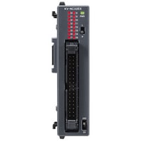
Information/Network unit
|
Model |
KV-XL202*1 |
KV-XL402*1 |
KV-XLE02*1 |
|||
|
Image |
|
|
|
|||
|
Type |
Serial communication unit |
Ethernet unit |
||||
|
Communication standard |
RS-232C |
RS-422A / RS-485 (4 wires), RS-422A / RS-485 (2 wires) |
||||
|
Connection interface |
European terminal block with 7 poles(detachable) × 2 ports |
European terminal block with 5 poles(detachable) × 2 ports |
RJ-45 8-position modular connector × 2 ports |
|||
|
Transmission specification |
Electrical termination (Terminator) |
― |
ON / OFF set by the switch on the front face |
|||
|
Transmission rate |
1,200, 2,400, 4,800, 9,600, 19,200, 38,400, 57,600, 115,200, 230,400 bps |
10BASE-T: 10 Mbps, 100BASE-TX: 100 Mbps,1000BASE-T :1,000 Mbps*6 |
||||
|
Transmission media |
10BASE-T: Category 3 or higher UTP or STP (STP is recommended) |
|||||
|
Transmission method |
Full duplex |
RS-422A / RS-485(4 wires): Full duplex, RS-422A / RS-485(2 wires): Half-duplex |
||||
|
Data format |
Start bit: 1 bit |
|||||
|
Error detection |
Parity: Even, odd, none |
|||||
|
RS/CS flow control |
ON or OFF |
ON or OFF(only in PLC link mode) |
||||
|
Transmission distance |
15 m |
Total extension: 1,200 m max.*4*5 |
||||
|
Number of transmission units |
1 |
32*4 |
||||
|
Maximum cable length |
100 m*8 |
|||||
|
Maximum number of connectable hubs |
10BASE-T: 4, 100BASE-TX: 2, 1000BASE-T: 1*9 |
|||||
|
Connectable CPU units |
KV-8000/KV-7500/KV-7300 |
|||||
|
Refreshes |
Automatic refresh, direct refresh,inter-unit synchronisation refresh |
Automatic refresh, direct refresh, inter-unit synchronisation refresh |
||||
|
Ethernet functions |
KV socket communication, PLC link, PROTOCOL STUDIO, |
|||||
|
Industrial networks |
EtherNet/IP®, PROFINET, EtherCAT*12, CC-Link IE Field*13*14 |
|||||
|
Serial communication functions |
Non-procedure, PROTOCOL STUDIO, Modbus RTU slave, etc. |
|||||
|
Ethernet function execution methods |
Ladder program, unit program (flow) |
|||||
|
Serial communication function execution methods |
Ladder program, unit program (flow) |
|||||
|
Unit program capacity |
3 MB (max. number of blocks: approx. 20,000) |
|||||
|
Flow |
Maximum number of flows |
256 |
||||
|
Number of simultaneous activities |
Unlimited |
|||||
|
Internal data memory |
524,288 words |
|||||
|
PROTOCOL STUDIO |
Transmission method |
Cyclic communication: Tx + Rx, Tx only, Rx only |
Cyclic communication: Tx + Rx, Tx only, Rx only |
|||
|
Maximum number of connected devices |
2 |
16 |
||||
|
Maximum number of communication commands |
48 / 96*2 |
160 / 320*15 |
||||
|
Maximum number of total frames |
Rx: 48 / 96*2 × 16; |
Rx: 160 / 320*15 × 16 Tx: 160 / 320*15 × 1 |
||||
|
Maximum number of compared and receive frames |
16 per command |
|||||
|
Maximum number of block elements |
96 per frame |
|||||
|
Transmission data length |
1 to 2,048 bytes per frame |
Standard: 1 to 2,048 bytes per frame |
||||
|
Received data length |
||||||
|
PLC link |
Communication patterns |
Write, read, transfer |
||||
|
Number of link settings |
512 settings max.*3 |
512 settings max.*16 |
||||
|
Link data size |
1,440 words max. per setting (bit: 720 words, word: 720 words) |
|||||
|
Data unit |
1 word |
|||||
|
Number of connected models |
2 models max.(1 model × 2 ports) |
16 models max.*16 |
||||
|
Number of connected units |
2 max.(1 unit × 2 ports) |
64 max.*16 |
||||
|
Trigger types |
Cyclic / event (64 settings max. for event*3) |
Cyclic / event (64 settings max. for event*16) |
||||
|
Update interval |
10 to 65,535 ms |
1 to 65,535 ms |
||||
|
Internal current consumption |
140 mA or less |
150 mA or less |
200 mA or less |
|||
|
Weight |
Approx. 200 g |
Approx. 190 g |
||||
|
*1 For KV-8000/KV-7000 Series |
||||||


DeviceNet® Unit
|
Model |
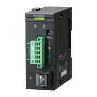
KV-DN20 |
|||
|
Image |
|
|||
|
Type |
DeviceNet® unit |
|||
|
Communication protocol |
Compliant with DeviceNet® |
|||
|
Transmission specification |
Transmission rate |
500 kbps, 250 kbps, 125 kbps |
||
|
Transmission media |
5 dedicated cables (2 for signal system, 2 for power, 1 for shield line) |
|||
|
Connection topology |
Multidrop method |
|||
|
Maximum cable length |
Thick main cable 500 m (Transmission speed 125 kbps), 250 m (Transmission speed 250 kbps), 100 m (Transmission speed 500 kbps) |
|||
|
Maximum number of nodes |
64 (including master, slave, configurator) |
|||
|
Master mode |
Connected pieces per network |
Max. 64 |
||
|
Type of communication |
I/O communication (Poll/Bit-Strobe/COS/Cyclic), Explicit message communication |
|||
|
Type and size of assigned devices |
Relay or data memory (indicated per block) |
|||
|
Assignment method of device |
Auto configuration (Fixed or assigned with front end) and manual assignment |
|||
|
Slave connection pieces per unit |
Max. 63 |
|||
|
Maximum number of I/O per slave |
Input: 2048 points (128 words), Output: 2048 points (128 words) |
|||
|
Data length of message communication |
Sending: 106 bytes, receiving 110 bytes |
|||
|
Slave mode |
Connected pieces per network |
Max. 64 |
||
|
Type of communication |
I/O communication (Poll), Explicit message communication |
|||
|
Type and size of assigned devices |
Relaying or data memory |
|||
|
Internal current consumption |
Internal circuit: 24 VDC 45 mA or less (supplied by CPU unit) |
|||
|
Weight |
Approx. 150 g |
|||
Camera input unit
|
Model |
KV-CA02*1 |
|||
|
Image |
|
|||
|
General specifications |
Power voltage |
System configuration using an expansion unit for KV-5000/3000 Series: |
||
|
Operating ambient temperature |
System configuration using an expansion unit for KV-5000/3000 Series: |
|||
|
Operating ambient humidity |
System configuration using an expansion unit for KV-5000/3000 Series: |
|||
|
Ambient temperature for storage |
System configuration using an expansion unit for KV-5000/3000 Series: |
|||
|
Storage relative humidity |
System configuration using an expansion unit for KV-5000/3000 Series: |
|||
|
Operating environment |
No dust or corrosive gas |
|||
|
Altitude |
2000 m or less |
|||
|
Noise immunity |
1500 Vp-p or more; |
|||
|
Withstand voltage |
1500 VAC for one minute |
|||
|
Insulation resistance |
50 MΩ or more |
|||
|
Vibration resistance |
Intermittent vibration |
Frequency 5 to 9 Hz |
Half amplitude: 3.5 mm*5 |
|
|
Frequency 9 to 150 Hz |
Acceleration: 9.8 m/s2*5 |
|||
|
Continuous vibration |
Frequency 5 to 9 Hz |
Half amplitude: 1.75 mm*5 |
||
|
Frequency 9 to 150 Hz |
Acceleration: 4.9 m/s2*5 |
|||
|
Shock resistance |
Acceleration: 150 m/s2, Application time: 11 ms, |
|||
|
Pollution degree |
2 |
|||
|
Performance specifications |
Connectable CPU unit |
KV-8000 |
||
|
Maximum number of connected units |
4 |
|||
|
Number of ports |
2 |
|||
|
Supported camera models |
KV-CA1H (Compact standard camera) |
|||
|
Cable length |
5/10/20 m*6 |
|||
|
Recording time |
Approx. 3 minutes*7 |
|||
|
Internal current consumption |
260 mA or less*8 |
|||
|
Weight |
Approx. 190 g |
|||
|
*1 For KV-8000 Series |
||||

Camera
|
Model |
KV-CA1H |
KV-CA1W |
|||
|
Image |
|
|
|||
|
General specifications |
Vibration resistance |
10 to 500 Hz |
|||
|
Operating ambient temperature |
0 to +50°C (no freezing) |
||||
|
Operating ambient humidity |
35 to 85% RH (no condensation) |
||||
|
Ambient temperature for storage |
-20 to +60°C (no freezing) |
||||
|
Storage relative humidity |
35 to 85% RH (no condensation) |
||||
|
Enclosure rating |
IP65F*1 *2 |
||||
|
Pollution degree |
3 |
||||
|
Performance specifications |
Installation distance |
200 mm to ∞ |
100 mm to ∞ |
||
|
Focal distance |
3.8 mm (fixed) |
1.05 mm (fixed) |
|||
|
Field of view |
Horizontal viewing angle: |
Horizontal viewing angle: |
|||
|
Image receiving element |
1/2.9 inch colour CMOS |
||||
|
Resolution |
640 (H) × 480 (V) |
1280 (H) × 960 (V) |
|||
|
Frame rate |
10/30/120 fps |
10/30 fps |
|||
|
Internal current consumption |
70 mA or less*3 |
||||
|
Weight |
Approx. 90 g |
Approx. 140 g |
|||
|
*1 The enclosure rating is evaluated with the camera cable connected. |
|||||


Power unit
|
Model |
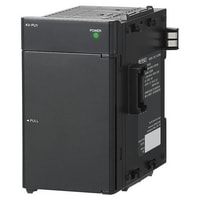
KV-PU1*1 |
|||
|
Image |
|
|||
|
Type |
AC power unit |
|||
|
Input supply voltage |
100 to 240 VAC (+10 %, -15 %) (50/60 Hz) |
|||
|
Output voltage |
24 VDC ±10% |
|||
|
Output capacity |
1.8 A (total power supply to various units and extra power supply) |
|||
|
Power consumption |
0.96 A or less |
|||
|
Momentary stop time |
20 ms or less (depending on rated I/O conditions) |
|||
|
Starting time |
Max. 3 sec. or less |
|||
|
Error output |
Output form |
Relay (NC contact) |
||
|
Rated load |
24 VDC 0.5 A |
|||
|
ON resistance |
50 mΩ or less |
|||
|
Response time |
OFF to ON: 10 ms or less, ON to OFF: 5 ms or less |
|||
|
Relay life |
Electrical: 100,000 times or more (20 times/min.), Mechanical: 20 million times or more |
|||
|
Relay exchange |
Impossible |
|||
|
Weight |
Approx. 300 g |
|||
|
*1 for KV-8000, KV-7000 Series |
||||
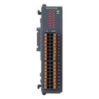
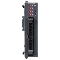
Remote I/O Expansion input unit
|
Model |
KV-NC16EX |
KV-NC16EXE |
KV-NC32EX |
|||
|
Image |
|
|
|
|||
|
Expansion input unit |
External connection method |
Connector |
European terminal block |
Connector |
||
|
Input Points |
16 points |
32 points |
||||
|
Input terminals |
24 VDC mode, 5 VDC mode |
|||||
|
Maximum input voltage |
26.4 VDC |
|||||
|
Input rated voltage |
24 VDC mode |
5.2 mA |
||||
|
5 VDC mode |
1 mA |
|||||
|
Minimum ON voltage |
24 VDC mode |
19 V |
||||
|
5 VDC mode |
3.5 V |
|||||
|
Maximum OFF voltage |
24 VDC mode |
1.5 mA |
||||
|
5 VDC mode |
1.5 V |
|||||
|
Common method |
16 points/1 common (2 terminals)*1 |
16 points/1 common (16 terminals) *2 |
32 points/1 common (2 terminals)*1 |
|||
|
Input time constant (four-level switching) |
Input time constant setting |
OFF to ON: Typ. |
25 µs: 10 µs |
|||
|
OFF to ON: Max. |
25 µs: 50 µs |
|||||
|
ON to OFF: Typ. |
25 µs: 50 µs |
|||||
|
ON to OFF: Max. |
25 µs: 150 µs |
|||||
|
Input impedance |
4.4 kΩ |
|||||
|
Internal current consumption |
20 mA or less |
|||||
|
Weight |
Approx. 100 g |
Approx. 120 g |
Approx. 110 g |
|||
|
*1 The KV-NX16EX and KV-NC32EX have 2 COM terminals, but these are shared internally. |
||||||
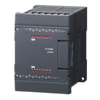
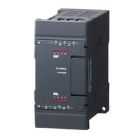
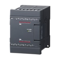
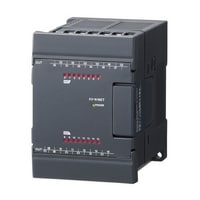
Remote I/O Expansion input unit
|
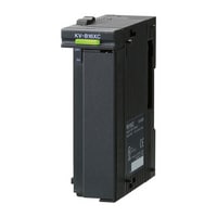
Model |
KV-N16EX |
KV-N8EX |
|||
|
Image |
|
|
|||
|
Expansion input unit |
External connection method |
Terminal block |
|||
|
Input terminals |
24 VDC mode, 5 VDC mode |
||||
|
Maximum input voltage |
26.4 VDC |
||||
|
Input rated voltage |
24 VDC mode |
5.3mA |
|||
|
5 VDC mode |
1mA |
||||
|
Minimum ON voltage |
24 VDC mode |
19V |
|||
|
5 VDC mode |
3.5V |
||||
|
Maximum OFF voltage |
24 VDC mode |
1.5mA |
|||
|
5 VDC mode |
1.5V |
||||
|
Common method |
16 points/1 common (2 terminals)*1 |
8 points/1 common (2 terminals)*1 |
|||
|
Input time constant (four-level switching) |
Input time constant setting |
OFF to ON: Typ. |
25µs : 10µs |
||
|
OFF to ON: Max. |
25µs : 50µs |
||||
|
ON to OFF: Typ. |
25µs : 50µs |
||||
|
ON to OFF: Max. |
25µs : 150µs |
||||
|
Input impedance |
4.3kΩ |
||||
|
Internal current consumption |
20mA or less |
||||
|
Weight |
Approx. 220 g |
Approx. 150 g |
|||
|
*1 The KV-N8EX and KV-N16EX have 2 COM terminals, but these are shared internally. |
|||||
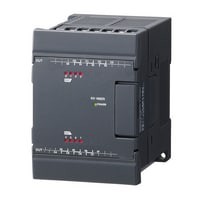
Remote I/O Expansion output unit
|
Model |
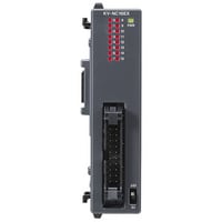
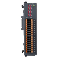
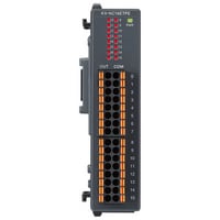
KV-NC16ETE |
KV-NC16ETPE |
KV-NC8ER |
|||
|
Image |
|
|
|
|||
|
Expansion output unit |
External connectionmethod |
MOSFET output (With overcurrent protection function)*1*2 |
Relay |
|||
|
External connection method |
European terminal block |
|||||
|
Rated load |
30 VDC, 0.2 A*3 |
250 VAC/30 VDC, 2 A |
||||
|
Leakage current (when output is OFF) |
100 µA or less |
― |
||||
|
Residual voltage (at ON) |
0.6 VDC or less |
|||||
|
ON resistance |
― |
50mΩ or less |
||||
|
Common method |
16 points/1 common (16 terminals)*4*5 |
4 points/1 common (4 terminals) *6 |
||||
|
Response time |
OFF to ON |
100 µs or less (with a load of 1 mA or more) |
10 ms or less |
|||
|
ON to OFF |
200 µs or less (with a load of 1 mA or more) |
|||||
|
Relay life |
― |
Electrical : 100,000 cycles or more (20 cycles/minute) Mechanical : 20,000,000 cycles or more |
||||
|
Relay replacement |
Not possible |
|||||
|
Internal current consumption |
30 mA or less |
70 mA or less |
||||
|
Weight |
Approx. 120 g |
Approx. 130 g |
||||
|
*1 If even a single overcurrent is detected, the protection operation (output turned OFF) and automatic recovery are repeated for all outputs within the shared common (The outputs within the shared common that are protected when an overcurrent is detected are outputs 000 to 007 or 008 to 015 for the KV-NC16ET(P) and KV-NC16ET(P)E.), until the cause of the problem is removed. |
||||||
Remote I/O Expansion output unit
|
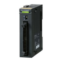
Model |
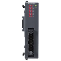
KV-NC16ET |
KV-NC16ETP |
KV-NC32ET |
KV-NC32ETP |
|||
|
Image |
|
|
|
|
|||
|
Expansion output unit |
External connectionmethod |
MOSFET output (With overcurrent protection function)*1*2 |
MOSFET output (With overcurrent protection function)*6*2 |
||||
|
External connection method |
Connector |
||||||
|
Rated load |
30 VDC, 0.2 A*3 |
||||||
|
Leakage current (when output is OFF) |
100 µA or less |
||||||
|
Residual voltage (at ON) |
0.6 VDC or less |
||||||
|
ON resistance |
― |
||||||
|
Minimum applicable load |
|||||||
|
Common method |
16 points/1 common (2 terminals)*4*5 |
32 points/1 common (2 terminals)*4*7 |
|||||
|
Response time |
OFF to ON |
100 µs or less (with a load of 1 mA or more) |
|||||
|
ON to OFF |
200 µs or less (with a load of 1 mA or more) |
||||||
|
Relay life |
― |
||||||
|
Relay replacement |
|||||||
|
Internal current consumption |
30 mA or less |
50 mA or less |
|||||
|
Weight |
Approx. 100 g |
Approx. 110 g |
|||||
|
*1 If even a single overcurrent is detected, the protection operation (output turned OFF) and automatic recovery are repeated for all outputs within the shared common (The outputs within the shared common that are protected when an overcurrent is detected are outputs 000 to 007 or 008 to 015 for the KV-NC16ET(P) and KV-NC16ET(P)E.), until the cause of the problem is removed. |
|||||||
Remote I/O Expansion output unit
|
Model |
KV-N16ER |
KV-N16ET |
KV-N16ETP |
|||
|
Image |
|
|
|
|||
|
Expansion output unit |
Output Points |
16 points |
||||
|
External connectionmethod |
Relay |
MOSFET |
||||
|
External connection method |
Terminal block |
|||||
|
Rated load |
250 VAC/30 VDC, 2 A |
30 VDC, 0.5 A |
||||
|
Leakage current (when output is OFF) |
− |
100 μA or less |
||||
|
Residual voltage (at ON) |
0.8 VDC or less (with 0.5 A output) |
|||||
|
ON resistance |
50 mΩ or less |
− |
||||
|
Common method |
4 points/1 common |
16 points/1 common |
||||
|
Response time |
OFF to ON |
10 ms or less |
100 μs or less (with a load of 1 mA or more) |
|||
|
ON to OFF |
200 μs or less (with a load of 1 mA or more) |
|||||
|
Relay life |
Electrical: 100000 cycles or more (20 cycles/minute) |
− |
||||
|
Relay replacement |
Impossible |
|||||
|
Internal current consumption |
100 mA or less |
40 mA or less |
||||
|
Weight |
Approx. 260 g |
Approx. 210 g |
||||
|
*1 The KV-N16ER has two terminals for each of C0, C1, C2, and C3 respectively, which are shorted internally. (C0, C1, C2, and C3 are independent.) |
||||||
Remote I/O Expansion output unit
|
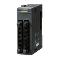
Model |
KV-N8ER |
KV-N8ET |
KV-N8ETP |
|||
|
Image |
|
|
|
|||
|
Expansion output unit |
Output Points |
8 points |
||||
|
External connectionmethod |
Relay |
MOSFET |
||||
|
External connection method |
Terminal block |
|||||
|
Rated load |
250 VAC/30 VDC, 2 A |
30 VDC, 0.5 A |
||||
|
Leakage current (when output is OFF) |
− |
100 μA or less |
||||
|
Residual voltage (at ON) |
0.8 VDC or less (with 0.5 A output) |
|||||
|
ON resistance |
50 mΩ or less |
− |
||||
|
Common method |
Independent |
8 points/1 common |
||||
|
Response time |
OFF to ON |
10 ms or less |
100 μs or less (with a load of 1 mA or more) |
|||
|
ON to OFF |
200 μs or less (with a load of 1 mA or more) |
|||||
|
Relay life |
Electrical: 100000 cycles or more (20 cycles/minute) |
− |
||||
|
Relay replacement |
Impossible |
|||||
|
Internal current consumption |
60 mA or less |
30 mA or less |
||||
|
Weight |
Approx. 230 g |
Approx. 160 g |
||||
|
*1 If even a single overcurrent is detected, the protection operation (output turned OFF) and automatic recovery are repeated for all outputs within the shared common ()The outputs within the shared common that are protected when an overcurrent is detected are outputs 000 to 007 or 008 to 015 for the case of the KV-N16ET(P)., until the cause of the problem is removed. |
||||||
Remote I/O Expansion I/O unit
|
Model |
KV-N8EXR |
KV-N8EXT |
|||
|
Image |
|
|
|||
|
Expansion input unit |
External connection method |
Terminal block |
|||
|
Input Points |
8 |
||||
|
Input terminals |
24 VDC mode, 5 VDC mode |
||||
|
Maximum input voltage |
26.4 VDC |
||||
|
Input rated voltage |
24 VDC mode |
5.3mA |
|||
|
5 VDC mode |
1mA |
||||
|
Minimum ON voltage |
24 VDC mode |
19V |
|||
|
5 VDC mode |
3.5V |
||||
|
Maximum OFF voltage |
24 VDC mode |
1.5mA |
|||
|
5 VDC mode |
1.5V |
||||
|
Common method |
8 points/1 common (1 terminal)*1 |
8 points/1 common (2 terminals)*1 |
|||
|
Input time constant (four-level switching) |
Input time constant setting |
OFF to ON: Typ. |
25µs : 10µs |
||
|
OFF to ON: Max. |
25µs : 50µs |
||||
|
ON to OFF: Typ. |
25µs : 50µs |
||||
|
ON to OFF: Max. |
25µs : 150µs |
||||
|
Input impedance |
4.3kΩ |
||||
|
Expansion output unit |
Output Points |
8 |
|||
|
External connectionmethod |
Relay |
MOSFET (N-ch) |
|||
|
Rated load |
250 VAC/30 VDC, 2 A |
30 VDC, 0.5 A |
|||
|
Leakage current (when output is OFF) |
― |
100µA or less |
|||
|
Residual voltage (at ON) |
0.8 VDC or less (with 0.5 A output), 0.6 VDC or less (with 0.3 A output) |
||||
|
ON resistance |
50mΩ or less |
― |
|||
|
Common method |
4 points/1 common |
8 points/1 common |
|||
|
Response time |
OFF to ON |
10ms or less |
100 µs or less |
||
|
ON to OFF |
200 µs or less |
||||
|
Relay life |
Electrical : 100000 cycles or more (20 cycles/minute) Mechanical : 20000000 cycles or more |
― |
|||
|
Relay replacement |
Not possible |
||||
|
Internal current consumption |
60mA or less |
30mA or less |
|||
|
Weight |
Approx. 230 g |
Approx. 210 g |
|||
|
*1 The input COM and output COM terminals are independent. |
|||||
Analog unit
|
Model |
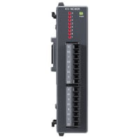
KV-N3AM |
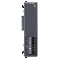
KV-NC2DA |
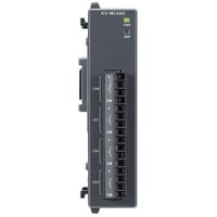
KV-NC4AD |
|||
|
Image |
|
|
|
|||
|
Conversion speed |
80 µs/channel*1 |
80µs/CH |
80 µs/channel*1 |
|||
|
Conversion |
A/D conversion, D/A conversion |
D/A conversion |
A/D conversion |
|||
|
Points |
A/D conversion : 2 (single end), D/A conversion : 1 |
2 |
4 (single end) |
|||
|
Range/resolution |
Voltage |
-10 V to +10 V |
A/D conversion : 1/8000 2.5 mV, D/A conversion : 1/8000 2.5 mV*2 |
1/8000 2.5mV |
||
|
0 to 10 V |
A/D conversion : 1/4000 2.5 mV, D/A conversion : 1/4000 2.5 mV*2 |
1/4000 2.5mV |
||||
|
0 to 5 V |
A/D conversion : 1/4000 1.25 mV, D/A conversion : 1/4000 1.25 mV*2 |
1/4000 1.25mV |
||||
|
1 to 5 V |
A/D conversion : 1/3200 1.25 mV, D/A conversion : 1/4000 1.25 mV*2 |
1/3200 1.25mV |
||||
|
Current |
0 to 20 mA |
A/D conversion : 1/4000 5 µA, D/A conversion : 1/4000 5 µA*2 |
1/4000 5µA |
|||
|
4 to 20 mA |
A/D conversion : 1/3200 5 µA, D/A conversion : 1/3200 5 µA*2 |
1/3200 5µA |
||||
|
Conversion precision |
Voltage |
Without temperature |
A/D conversion : ±0.3% of F.S. (at 25°C ±5°C), ±0.5% of F.S. (at 0 to 55°C), D/A conversion : ±0.3% of F.S. (at 25°C ±5°C), ±0.5% of F.S. (at 0 to 55°C) |
±0.3% of F.S. (at 25°C ±5°C) |
||
|
With temperature |
A/D conversion : ±0.3% of F.S. (at 25°C ±5°C), D/A conversion : ±0.3% of F.S. (at 25°C ±5°C), ±0.5% of F.S. (at 0 to 55°C) |
±0.3% of F.S. (at 25°C ±5°C) |
±0.3% of F.S. (at 0 to 55°C) |
|||
|
Current |
Without temperature |
A/D conversion : ±0.4% of F.S. (at 25°C ±5°C), ±0.6% of F.S. (at 0 to 55°C), D/A conversion : ±0.3% of F.S. (at 25°C ±5°C), ±0.5% of F.S. (at 0 to 55°C) |
±0.4% of F.S. (at 25°C ±5°C) |
|||
|
With temperature |
A/D conversion : ±0.4% of F.S. (at 25°C ±5°C), D/A conversion : ±0.3% of F.S. (at 25°C ±5°C), ±0.5% of F.S. (at 0 to 55°C) |
±0.4% of F.S. (at 0 to 55°C) |
||||
|
Input resistance |
Voltage |
A/D conversion : 5MΩ |
― |
5MΩ |
||
|
Current |
A/D conversion : 250MΩ |
250Ω |
||||
|
Absolute maximum input |
Voltage |
A/D conversion : ±15V |
±15V |
|||
|
Current |
A/D conversion : ±30mA |
±30mA |
||||
|
Isolation method |
Between analogue input |
Isolated (photocoupler, transformer) |
||||
|
A/D , D/A conversion unit |
Isolation method |
Between Analogue input - output |
Non-isolated |
|||
|
Isolation method |
Between analogue input channels |
A/D conversion : Non-isolated |
Non-isolated |
|||
|
Minimum load resistance |
Voltage |
D/A conversion : 1kΩ |
1kΩ |
― |
||
|
Maximum load resistance |
Current |
D/A conversion : 600kΩ |
600Ω |
|||
|
Special functions |
▼A/D conversion |
Output range switching, output data offset, |
Input range switching, |
|||
|
Internal current consumption |
120mA or less |
|||||
|
Weight |
200 g |
|||||
|
*1 When the temperature fluctuation compensation is used, the temperature fluctuation compensation time of 80 µs will be added regardless of the number of channels being used. |
||||||
Temperature input unit
|
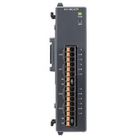
Model |
KV-NC4TP |
|||
|
Image |
|
|||
|
Temperature input unit |
Number of inputs |
4*1 |
||
|
Input |
Thermocouple, Platinum resistance thermometer |
|||
|
Input range |
Thermocouple |
K : -270.0 to 1372.0˚C |
||
|
Platinum resistance thermometer |
Pt100 : -200.0 to 850.0˚C |
|||
|
Overall accuracy |
Thermocouple |
±0.2% of F.S. (at 25°C ±5°C) |
||
|
Platinum resistance thermometer |
||||
|
Allowable wiring resistance |
Platinum resistance thermometer |
100 Ω max./wire |
||
|
Conversion speed |
125ms/ch |
|||
|
Isolation method |
Between input terminals and base unit : |
|||
|
Special functions |
Channel skip, disconnection detection, |
|||
|
Internal current consumption |
40mA or less |
|||
|
Weight |
Approx. 110 g |
|||
|
*1 Individual setting is possible for each channel. |
||||